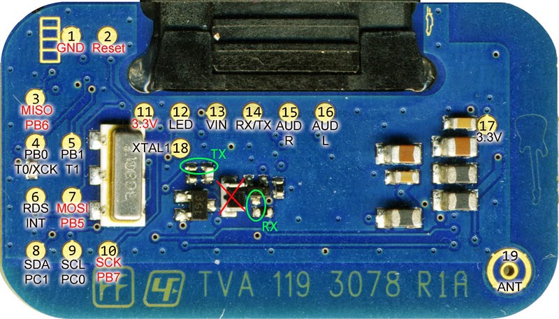
To build the FMBerry transmitter, you just need to connect specific testpoints on the PCB of the MMR70 to your Raspberry Pi.
Thanks to Oliver J. (skriptkiddy) for the schematics and the photo with all named testpoints. Thanks to Andrey Chilikin for the excellent photo with all testpoints labeled.
Old IDE (40pin!) or Floppy Cable does an excellent job for connecting to your Pi. Begin by simply connecting these pins together:
- GND -- TP18
- GND -- TP2 (Thanks to Thomas H. for the note!)
- GND -- TP1
- 3V3 -- TP11
- SDA -- TP8
- SCL -- TP9
- #17 -- TP6 (RDS Interrupt)
External antenna, a wire (300/(frequency in MHz) * 25) cm long, can be connected to TP19 or to TP20 - the only testpoint on back side of MMR-70
Very important!
Now you need to disable the internal processor of the transmitter. This can be done easily by shorting on of it's crystal pins. To do this connect TP18 to GND and TP2 to GND!
Be aware that MMR-70 can consume up to 27 mA, so make sure that you do not overload Raspberry Pi 3.3V supply (recommended maximim 3.3V current ~55mA)
Get yourself an old 3,5" phono plug. I've got mine from an old pair of cellphone speakers. Connect it as following:
- Audio GND -- TP1
- Audio R -- TP15
- Audio L -- TP16
After soldering (and checking)
plug it into your Raspberry Pi.
That's it! =)


