| Information | |
|---|---|
| Document Owner | Maxime CARON |
| Creation Date | 2024/09/23 |
| Last Update Date | 2024/10/11 |
| Document Name | Technical Specifications - Frogger [Team 6] |
| Version n° | Author | Date | Description of edits |
|---|---|---|---|
| 0.01 | Maxime CARON | 2024/09/23 | Document skeleton |
| 0.02 | Maxime CARON | 2024/10/01 | Reworked structure |
| 0.03 | Maxime CARON | 2024/10/02 | Add technical specifications |
| 1.00 | Maxime CARON | 2024/10/11 | First complete version |
Click to expand
| Term | Description | Source |
|---|---|---|
| Code Completion | A feature in IDEs that suggests possible completions for partially typed code, improving efficiency. | Wikipedia |
| FPGA | Field Programmable Gate Array - A type of hardware used to implement digital circuits. | Wikipedia |
| Frogger | A classic 1981 arcade game where players control a frog attempting to cross a busy road and river. | Wikipedia |
| IDE | Integrated Development Environment - Software used for writing, compiling, and debugging code. | Wikipedia |
| NandLand | A company that provides educational FPGA hardware and learning resources, such as the GO Board. | NandLand |
| Syntax Highlighting | A feature in IDEs that displays code in different colors and fonts to differentiate between elements. | Wikipedia |
| SystemVerilog | An extension of Verilog with additional features for system-level design, verification, and simulation. | Wikipedia |
| Testbenches | Simulations that verify the functionality of a digital circuit by applying inputs and comparing outputs. | Intel |
| Verilog | A hardware description language (HDL) used to model and simulate digital systems at the RTL level. | Wikipedia |
This document outlines the technical aspects of the Frogger game project, building upon the functional specifications. It defines the technical details, scope, and features of the game to ensure that the development follows the guidelines and meets project objectives.
To gain a full understanding of the project, it is recommended to first review the Functional Specifications.
This document also serves as a technical reference for development, detailing conventions, tools, and methodologies that will enhance project scalability and maintainability.
The goal of this project is to create a hardware implementation of the Frogger game using the NandLand GO Board and Verilog. The game will feature movement, collision detection, and scoring mechanisms.
Our vision is to recreate the classic Frogger gameplay with personalized graphics and additional features that enhance player engagement. The game will run on the NandLand GO Board, offering a fun and interactive experience.
Key assumptions for this project:
- The NandLand GO Board is fully operational.
- Verilog code is correctly implemented and works as expected on the FPGA.
- The functional requirements, such as movement and collisions, are properly implemented.
- The game provides smooth performance without critical bugs or errors.
The NandLand GO Board is an FPGA development board used for creating digital circuits with Verilog. It features LEDs, push buttons, a VGA connector, and other components that make it ideal for hardware projects.
GO Board pinout can be found here.
The NandLand GO Board features the following components:
FPGA (ICE40HX1K-VQ100): The board's programmable chip, responsible for running the Verilog code. It contains 65,536 memory bits.
All details about the chip can be found here
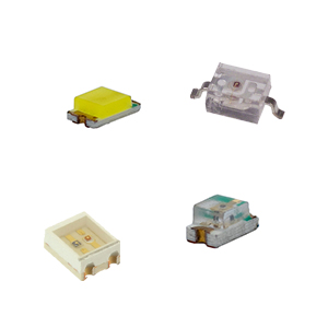
LEDs: 4 programmable LEDs and 1 power indicator.
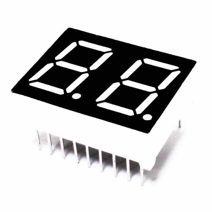
7-Segment Displays: Two displays for showing numeric values, such as score or timer.
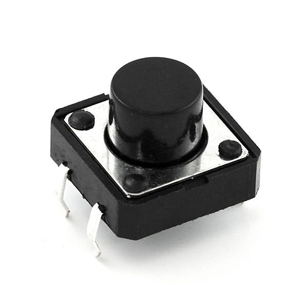
Push Buttons: Four input buttons, useful for player movement and interactions.
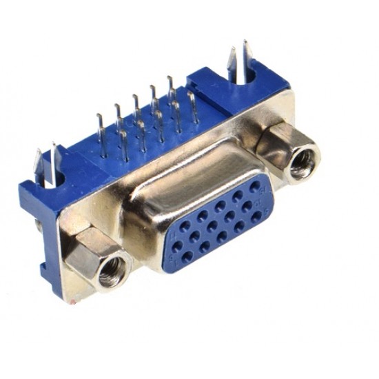
VGA Connector: A port for connecting an external monitor to display the game.
Micro USB Connector: Used for power supply and FPGA programming.
PMOD Connector: Expands the board's functionality by allowing external modules.
Board schematics can be found in appendix here.
Follow the setup tutorial to configure your development environment for the NandLand GO Board.
The project will use Verilog to design and implement the game's logic, while SystemVerilog will be employed to create testbenches for verifying the Verilog modules.
Verilog is a popular hardware description language for designing digital circuits. It enables the modeling and simulation of hardware components like logic gates and flip-flops.
Here's an example of a simple AND gate in Verilog:
// This module implements an AND gate
module and_gate(input a, input b, output y);
    assign y = a & b;
endmodule
For more details, see the Verilog introduction tutorial.
SystemVerilog extends Verilog, adding features like object-oriented programming and advanced testing tools. It is particularly useful for creating testbenches to verify Verilog designs.
Example of a counter using SystemVerilog:
// This module implements a simple counter
module counter;
    int count = 0; // Counter variable

    // Counter logic
    initial begin
        while (1) begin
            $display("Count: %d", count);
            count = count + 1;
            #1;
        end
    end
endmoduleTo write and test Verilog code, users can use a text editor or an integrated development environment (IDE) such as Visual Studio Code, Xilinx Vivado, or Quartus Prime. These tools provide features such as syntax highlighting, code completion, and debugging capabilities to help users write and test Verilog code efficiently.
Every conventions used in the project are detailed in the appendix 1 - project conventions.
The visual representation of the game is one of the core components, as it engages the player and enables interaction. Below are the key details regarding the display system for the Frogger game.
The game graphics are designed to provide a visually appealing and engaging experience for the player. These graphics include elements such as the player character, enemies, obstacles, and background scenery to create an immersive game environment.
Details of the graphics are provided in the Functional Specifications.
The game will run on the NandLand GO Board's display, with a resolution of 640x480 pixels. Game elements will be appropriately scaled and positioned to fit the screen size, ensuring an optimal viewing experience for the player.
The Verilog code will configure the display resolution to ensure proper rendering of game elements on the screen. The game logic will handle adjustments to the display resolution to ensure that the graphics and gameplay remain aligned with the intended visual presentation.
A grid system will be employed to manage the positioning and movement of game elements on the screen. The grid will divide the display into cells, allowing for precise placement and movement of objects in discrete steps.
The screen will be divided into a grid consisting of 20 columns and 15 rows. Each cell will represent a specific coordinate on the screen, simplifying the handling of movement and interactions.
The game elements such as the player character, enemies, obstacles, and background scenery will be represented using sprites. Sprites are 2D images that provide visual representations of these elements.
Each sprite will have a resolution of 32x32 pixels, ensuring detailed and recognizable graphics. These sprites will be designed to be visually distinct and easily recognizable by the player.
The game will use Block RAM (BRAM) to store the game state, player position, enemy positions, and other relevant data. BRAM provides fast and efficient memory access, making it ideal for storing and retrieving game data during runtime.
The game logic will manage the BRAM to store and update the game state, ensuring that the data is accessible and accurate at all times. The BRAM will be used to store game elements, player lives, score, and other game-related information.
graph TD
    A[Initialize Game State] --> B[Store Game State in BRAM]
    B --> C[Update Game State]
    C --> D[Retrieve Game State from BRAM]
    D --> E[Display Game State]
Each player movement is managed by the movement module. Every movement is controlled by the player input. The player can move forward, backward, left, and right on the screen.
The player can move using the following inputs:
- SW1 (Go Board switch 1): The player moves forward by one cell.
- Controller red button (PMOD PIN 4): The player moves forward by one cell.
- SW4 (Go Board switch 4): The player moves backward by one cell.
- Controller yellow button (PMOD PIN 2): The player moves backward by one cell.
- SW2 (Go Board switch 2): The player moves left by one cell.
- Controller blue button (PMOD PIN 1): The player moves left by one cell.
- SW3 (Go Board switch 3): The player moves right by one cell.
- Controller green button (PMOD PIN 3): The player moves right by one cell.
The player movement logic will be implemented in Verilog following the activity diagram below:
graph TD
    AA[Controller Red Button Pressed] --> B
    A[SW1 Pressed] --> B[Check If Player Can Move Forward]
    B --> D[Is Player Can Move Forward?]
    D --> |Yes| E[Move Forward]
    D --> |No| F[Do Nothing]
    E --> G[Update Player Position]

    HH[Controller Yellow Button Pressed] --> I
    H[SW4 Pressed] --> I[Check If Player Can Move Backward]
    I --> K[Is Player Can Move Backward?]
    K --> |Yes| L[Move Backward]
    K --> |No| M[Do Nothing]
    L --> N[Update Player Position]

    OO[Controller Blue Button Pressed] --> P
    O[SW2 Pressed] --> P[Check If Player Can Move Left]
    P --> R[Is Player Can Move Left?]
    R --> |Yes| S[Move Left]
    R --> |No| T[Do Nothing]
    S --> U[Update Player Position]

    VV[Controller Green Button Pressed] --> W
    V[SW3 Pressed] --> W[Check If Player Can Move Right]
    W --> Y[Is Player Can Move Right?]
    Y --> |Yes| Z[Move Right]
    Y --> |No| YY[Do Nothing]
    Z --> ZZ[Update Player Position]
Enemies will move horizontally across the screen, either left-to-right or right-to-left, depending on the lane they occupy.
Enemies will be generated at pseudo-random intervals. The generation logic will be handled by a linear feedback shift register (LFSR), a simple pseudo-random number generator. This ensures that enemies appear at different times but follow a controlled pattern.
    graph TD
    Start[Start] --> LFSR[Linear Feedback Shift Register]
    LFSR -->|Generates pseudo-random number| Timer[Enemy Spawn Timer]
    Timer -->|Interval reached| GenerateEnemy[Generate Enemy]
    GenerateEnemy --> UpdateGame[Update Game State]
    UpdateGame --> LFSR
-
Movement Speed: Each lane will have enemies with a specific, predefined speed. For instance, cars may travel faster than logs. This speed is consistent for all enemies within a given lane but can vary between different lanes to create dynamic movement patterns.
-
Wrap-Around Movement: When an enemy exits one side of the screen, it will seamlessly reappear on the opposite side, simulating continuous, looping movement. This ensures the game’s flow remains uninterrupted as enemies continuously traverse the screen.
graph TD
    A[Initialize Enemy Position] --> B[Move Enemy]
    B --> C[Is Enemy Off Screen?]
    C --> |No| B
    C --> |Yes| E[Reposition Enemy to Opposite Side]
    E --> F[Update Enemy Position]
    F --> B
To detect collisions between game elements, the program will check the position of each element in the grid and determine if any elements are overlapping. The collision module will handle the detection of collisions and trigger the appropriate actions based on the collision type.
The collision module will check for collisions between the player and enemies, obstacles, water, and other game elements. When a collision is detected, the collision module will trigger the corresponding behavior based on the collision type.
graph TD
    A[Check for Collision] --> B[Check for Player-Enemy Collision]
    B --> C[Is Player Collides with Enemy?]
    C --> |No| D[Do Nothing]
    C --> |Yes| E[Player Loses Life]
    E --> F[Is Player Out of Lives?]
    F --> |Yes| G[Game Over]
    F --> |No| H[Player Respawn at Level Start]
When the player reaches the water, the player will lose a life. The water collisions will be managed by the collision module, which will detect when the player reaches the water and trigger the appropriate action.
graph TD
    A[Check for Collision] --> B[Check for Player-Water Collision]
    B --> C[Is Player Collides with Water?]
    C --> |No| D[Do Nothing]
    C --> |Yes| E[Player Loses Life]
    E --> F[Is Player Out of Lives?]
    F --> |Yes| G[Game Over]
    F --> |No| H[Player Respawn at Level Start]
When the player reaches the edge of the screen, the player will not be able to move further in that direction. The wall collisions will be managed by the collision module, which will detect when the player reaches the edge of the screen and prevent further movement in that direction.
graph TD
    A[Check for Collision] --> B[Check for Player-Wall Collision]
    B --> C[Is Player Collides with Wall?]
    C --> |No| D[Do Nothing]
    C --> |Yes| E[Prevent Player Movement]
Enemy collisions will be managed by the collision module. The collision module will check for collisions between the player and enemies, obstacles, and other game elements. When a collision is detected, the appropriate action will be taken based on the collision type.
graph TD
    A[Check for Collision] --> B[Check for Player-Enemy Collision]
    B --> C[Is Player Collides with Enemy?]
    C --> |No| D[Do Nothing]
    C --> |Yes| E[Player Loses Life]
    E --> F[Is Player Out of Lives?]
    F --> |Yes| G[Game Over]
    F --> |No| H[Player Respawn at Level Start]
When the player reaches the top of the screen, the player wins the game. The win condition will be triggered when the player reaches the top row of the grid. Then the level will be incremented and the player will move to the next level.
The game will feature multiple levels, each with increasing difficulty and challenges. The difficulty is represented by the speed of the enemies, every 3 levels the speed of the enemies will increase by 5%. The speed of the enemies.
The level system will be implemented in Verilog following the activity diagram below:
graph TD
    A[Player Wins] --> Z[Increase Level By 1]
    Z --> B[Check if Level is a Multiple of 3]
    B --> C[Is Level is a Multiple of 3?]
    C --> |Yes| E[Increase Enemy Speed By 5%]
    E --> F[Update Level Display]
    C --> |No| F
The game will also be playable using controllers connected to the PMOD connector. These controllers will allow the player to control the movement of the player character in the game. The Verilog code will read the inputs from the controllers via the PMOD connector to update the character's position.
The controllers provide the following inputs for player movement:
- Red Button: Moves the player character forward by one cell.
- Yellow Button: Moves the player character backward by one cell.
- Blue Button: Moves the player character left by one cell.
- Green Button: Moves the player character right by one cell.
These inputs are mapped to the corresponding player movements. The Verilog code will handle reading these inputs and translate them into actions that adjust the player character's position on the screen.
More details about the movement logic can be found in the Movement section.
The controllers are connected to the PMOD connector on the NandLand GO Board, which provides a convenient interface for external modules. Each button on the controller corresponds to a specific player movement, allowing for precise control in the game.
The controller's design uses simple push buttons wired to the PMOD pins on the FPGA board. When a button is pressed, the system registers the input, and the character's movement is updated accordingly.
Below is the electronic schematic for the controller:
As outlined in the Functional Specifications, both the controller and the FPGA board will be housed in custom-designed casings. These casings have been designed using Solidworks for Makers to ensure proper fit and functionality.
All components are available in the 3D Models folder.
The 3D models will be fabricated using a 3D printer. The physical components of the controller and the FPGA board casing will be created from the provided 3D models using PLA filament.
Here are the recommended parameters for 3D printing:
- Filament: PLA
- Layer Height: 0.2mm
- Infill: 15%
- Print Speed: 60mm/s
- Temperature: 200°C (Extruder), 60°C (Bed)
The printed components will match the design specifications of the 3D models to ensure proper assembly and functionality.

