This document describes how the lorawan-server handles LoRaWAN communication with active network Nodes.
The server can be connected to one or more LoRaWAN gateways. All gateways act as one distributed antenna, common to all Networks:
- The server receives device uplinks from all gateways that received the signal, regardless to which Network does the device belong.
- Downlinks are them sent to the gateway that indicated best RSSI (Received Signal Strength Indication).
The server can handle one or more networks. Each Network configuration covers:
- Network Identifier used to create DevAddr for newly joined nodes
- LoRaWAN Regional Parameters, including additional frequencies (channels)
Each LoRaWAN network contains various devices.
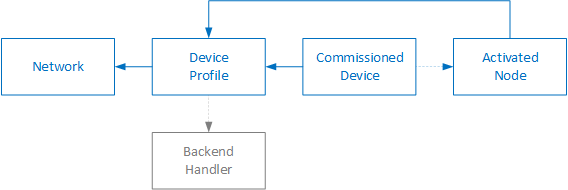
(Device) Profile represents one particular hardware and all static settings in the firmware, common for a group of devices. The configuration includes:
- Reference to a particular Network
- Ability of the device to perform ADR or provide battery status
- Application (syntax and semantics of the frames)
In addition to that, each Profile may belong to one or more multicast channels.
Represents commissioning parameters for Over-the-Air Activation (OTAA) of one particular device. The configuration includes:
- Reference to a particular Profile
- DevEUI, AppEUI and AppKey
Represents devices Activated-By-Personalization (ABP) and Over-the-Air Activated (OTAA) devices that already joined the network. The configuration includes:
- Reference to a particular Profile
- DevAddr, NwkSKey and AppSKey
- Frame counters, actual ADR settings and statistics
Backend servers provide external applications, which receive and process uplink frames and (optionally) send downlink frames.
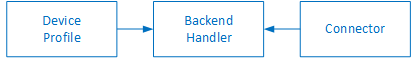
Handlers define externally handled application, including:
- Format of the uplink and downlink messages
- Data fields forwared via the backend Connectors
- Retransmission logic for confirmed downlinks
Each Handler may be linked with one or more backend Connectors, which handle the communication towards the backend server.
Connectors define transport of data fields to/from external servers. Each connector is linked with one Handler and specifies:
- Communication protocol
- Target endpoint, i.e server address and message topics
- Encoding of the data fields
When a Node sends a LoRaWAN frame (message) it gets received by one (or multiple) gateways. The gateways are very simple and just forward all received frames to the server.
Upon receiving an uplink frame the server:
- Filters duplicate frames, which were received by multiple gateways.
- Verifies the message integrity check and decrypts application data.
- Compares the received Frame Counter (FCnt Up) with the previously received
FCnt Up to identify retransmissions:
- If the FCnt Up increased the respective Application Handler gets invoked.
- If the FCnt Up is the same the device just retransmitted the previous frame. The frame gets logged in the Received Frames list, but handler is not invoked.
- If the FCnt Up decreased an error Event is generated, unless the FCnt Up did reset and the Node FCnt Check is set to Reset on zero. Such frames are processed as if the FCnt Up increased.
Every LoRaWAN device can transmit for a short time only, usually 0.1% or 1% depending on frequency. LoRaWAN is thus not suitable for continuous transmissions.
| Duty | Total TX in 1 hour | Each TX | Gap between TX |
|---|---|---|---|
| 0.1% | < 3.6s | < 0.72s | > 0.72s |
| 1% | < 36s | < 3.6s | > 1.8s |
LoRaWAN devices can be Class A, B or C.
Class A devices listen for downlink frames only for few seconds after sending an uplink frame. This is the default and most common behaviour.
Upon receiving a downlink frame for a given Node:
- When the Node just sent an uplink frame the server sends the downlink frame immediately to the closest Gateway, which forwards the frame to the device.
- When the Node did not send anything the frame gets queued in the server and waits for the Node to send a next uplink. The queued Downlinks can be viewed via the Node Administration.
The downlink frequencies and data rates are defined by the Network.
Currently not supported.
Class C devices listen for downlink frames constantly.
The server has no knowledge if a particular device is Class A or C. It assumes the applications (somehow) know this.
When initiating a downlink applications can set requested downlink time. This
can be either a specific timestamp, or an immediately flag. See the
Downlink Fields documentation for more details.
Upon receiving a downlink frame with the time parameter set the server sends the frame to the gateway and relies on its scheduling mechanism to transmit the frame.
It is possible to send one downlink frame to multiple Class C devices. First,
a multicast channel needs to be defined both in the network
Infrastructure and also in the device (see struct sMulticastParams
in LoRaMac-node). The multicast DevAddr
is a special dedicated address that must not collide with any Node address.
To send a multicast downlink the application simply initiates a downlink with:
- DevAddr that was previously defined as a multicast channel.
- time parameter set to a given timestamp, or to the
immediatelyflag.