?> Zigbee2Tasmota serves as a gateway for devices connected to a Zigbee wireless network to bridge their communications over to Wi-Fi.
Zigbee2Tasmota is a lightweight Zigbee solution running on an ESP82xx Wi-Fi chip. Hence it is easier to deploy in your living room or around your home. It is largely inspired from Zigbee2mqtt but it's a complete rewrite to make it fit on an ESP82xx with 80kB of RAM and only 1MB of flash memory.
Before using Zigbee to Tasmota, you need to understand a few concepts. Here is a simplified comparison to the Wi-Fi equivalent (sort of).
| Zigbee concept | Wi-Fi equivalent |
|---|---|
| Zigbee coordinator The coordinator is responsible for selecting the channel, PanID, security policy, and stack profile for a network. Zigbee2Tasmota will act as a coordinator. You can have multiple coordinators as long as they have different PanIDs. |
Wi-Fi Access Point |
| PanID (Personal Area Network IDentifier) This parameter is unique in a Zigbee network. The PanID is a 16-bit integer. Default: 0x1A63 |
SSID (the Wi-Fi network name) |
| ShortAddr Address of the device on the Zigbee network. This address is randomly assigned when the device first connects to the coordinator. The coordinator has address 0x0000. You need to track which device has which address. There is currently no "Friendly Name" mechanism. This may be added in the future. |
IP address |
| Endpoint The endpoint on the coordinator or on the Zigbee device the message is sent from/to. You can see endpoints as logical device providing distinct features |
IP Port |
| IEEEAddr Device hardware address (64 bits). This is unique per device and factory assigned. |
MAC address |
| Channel 11-26 Default: 11 |
Wi-Fi Channel |
| Encryption Key 128-bit encryption key. default: 0x0D0C0A08060402000F0D0B0907050301 |
Wi-Fi password |
| Pairing By default the coordinator does not accept new devices unless put in pairing mode. When in pairing mode, it will accept pairing requests from any device within range. Default: pairing disabled |
WPS |
You cannot use any CC2531 based device with Tasmota! CC2531 supports USB communication and not serial communication required by Zigbee2Tasmota.
| CC2530 with PCB antenna, DL-20 | CC2530 with external antenna | CC2530 with external antenna and CC2591 RF front end |
|---|---|---|

|

|

|
Using an ESP82xx device such as a Wemos D1 Mini or a NodeMCU to flash the CC2530 (described below) is a lower cost alternative than using a single purpose CC_DEBUGGER. When in normal operation, this ESP82xx device can then also serve as the Wi-Fi adapter for the Zigbee2Tasmota messaging.
In normal operation, only two free GPIO are needed for the serial communications with the CC2530. You can use the ESP82xx device above to flash the CC2530 adapter(s) and then use any other ESP82xx device flashed with Zigbee2Tasmota as the gateway between Zigbee and Wi-Fi.
Zigbee2Tasmota requires a TI CC2530 based module flashed with Z-Stack-firmware from Koen Kanters. To simplify this procedure, a ready to use fork of the needed firmware files is available.
A. Flash CCLib on an ESP82xx Device
Flashing the CC2530 normally requires a CC_DEBUGGER. Using an ESP82xx device like a Wemos D1 Mini is a lower cost alternative.
If you are using a Wemos D1 Mini or NodeMCU, just plug the microUSB port. Vcc (3.3V), GND, Tx (GPIO1), and Rx (GPIO3) are connected via the microUSB port. Be sure that you are using a USB data cable.
For ESP devices that do not have a microUSB connector, make the following connections:
ESP Device |
Serial Programming Adapter |
|---|---|
| Vcc | Vcc |
| GND | GND |
| GPIO0 | GND |
| GPIO1 | Rx |
| GPIO3 | Tx |
Follow the usual ESP82xx flashing process - you are just using CCLib_proxy.ino.bin instead of Tasmota.
Once the firmware upload completes, retain the serial interface connections (3.3V, GND, Tx, Rx). These will be used later for flashing the CC2530.
B. Connect the CC2530 and the ESP82xx
The DL-20 Zigbee module has a 5-pin 1.27mm pitch unpopulated header with 0.6mm througholes. For flashing any of the Zigbee modules, you need the following connections:
| ESP Pin |
D1 Mini NodeMCU |
CC2530 Pin |
DL-20 J2 Pin Location |
|---|---|---|---|
| GPIO12 | D6 | CC_DD (A.K.A. P2_1 or Debug Data) |
5 |
| GPIO4 | D2 | CC_DC (A.K.A. P2_2 or Debug Clock) |
4 |
| Vcc | 3.3v | Vcc | 3 |
| GPIO5 | D1 | CC_RST | 2 |
| GND | GND | GND | 1 |
DL-20 Flashing Jumpers
Insert alternating male Dupont jumpers; one jumper on one side, the next one on other side. This allows the pins to provide the friction themselves to maintain contact and remain firmly in place. You only need DD, DC, and RST (a fourth jumper is shown which is used to keep the RST jumper in place). Vcc and GND are available on the main serial interface pins.

Prototype


C. Upload the firmware to the CC2530
The CC2530 requires Z-Stack_Home_1.2, of type Default (not Source Routing). For convenience, ready to use firmware files are provided. Select the right one for your hardware: CC2530, CC2530 + CC2591 or CC2530 + CC2592.
These Python scripts require Python 2.7.
-
Ensure that you have Python 2.7 installed
-
Install pyserial 3.0.1:
pip install pyserial==3.0.1 -
Check for connectivity before flashing:
python Python/cc_info.py -p <serial_port>where <serial_port> is the serial port for the ESP82xx device. e.g.
/dev/cu.usbserial-xxxxorCOM7Example of result:
INFO: Found a CC2530 chip on /dev/cu.usbserial-xxxx

Chip information:
      Chip ID : 0xa524
   Flash size : 16 Kb
    Page size : 2 Kb
    SRAM size : 1 Kb
          USB : No

Device information:
 IEEE Address : 000000000000
           PC : 0000

Debug status:
 [ ] CHIP_ERASE_BUSY
 [ ] PCON_IDLE
 [X] CPU_HALTED
 [ ] PM_ACTIVE
 [ ] HALT_STATUS
 [X] DEBUG_LOCKED
 [X] OSCILLATOR_STABLE
 [ ] STACK_OVERFLOW

Debug config:
 [ ] SOFT_POWER_MODE
 [ ] TIMERS_OFF
 [ ] DMA_PAUSE
 [ ] TIMER_SUSPEND
If your CC2530 is DEBUG_LOCKED, then the flash size will be incorrectly reported as 16kB which is not big enough to fit the Z-Stack firmware. To fix this you need to reset the DEBUG_LOCKED flag. This can be accomplished by erasing the chip. The easiest method is to flash the chip specifying the erase option. You will need any 16kb file to flash. Read the existing flash from the chip and then re-flash that file using the erase option.
python Python/cc_read_flash.py -p <serial_port> -o x.hex
python Python/cc_write_flash.py --erase -p <serial_port> -i x.hex
Recheck for connectivity and the the correct flash size by repeating step #3.
-
Flash the Z-Stack firmware using the following command:
Flashing the CC2530 takes about 30 minutespython Python/cc_write_flash.py -e -p <serial_port> -i Bin/CC2530_DEFAULT_20190608_CC2530ZNP-Prod.hexINFO: Found a CC2530 chip on /dev/cu.usbserial-xxxx Chip information: Chip ID : 0xa524 Flash size : 256 Kb Page size : 2 Kb SRAM size : 8 Kb USB : No Sections in Bin/CC2530_DEFAULT_20190608_CC2530ZNP-Prod.hex: Addr. Size -------- ------------- 0x0000 8176 B 0x1ff6 10 B 0x3fff0 1 B 0x2000 239616 B This is going to ERASE and REPROGRAM the chip. Are you sure? <y/N>: y Flashing: - Chip erase... - Flashing 4 memory blocks... -> 0x0000 : 8176 bytes Progress 100%... OK -> 0x1ff6 : 10 bytes Progress 100%... OK -> 0x3fff0 : 1 bytes Progress 100%... OK -> 0x2000 : 239616 bytes Progress 100%... OK CompletedIf you don't see any on screen activity that flashing has begun (i.e., progress percentages increasing) within a couple minutes, then abort the command, cycle power on the ESP82xx, and start this step over.
Additional References:
- Flashing with a Wemos D1 Mini or equivalent and
CCLibis described in greater detail in this blog post. - Koen Kanters Z-Stack CC2530 firmware files.
- There are many tutorials online on how to flash a CC2530 with a dedicated CC_DEBUGGER.
Once the CC2530 flashing process completes, you can re-use that ESP82xx device by flashing it with the Zigbee2Tasmota firmware. Otherwise, you can use any ESP82xx device.
- Compile Tasmota
#define USE_ZIGBEEinuser_config_override.h.
- Follow the usual Tasmota flashing process
The connection uses a 115200 baud serial connection. Hence you need to configure two GPIOs: Zigbee TX and Zigbee RX.
If you are using your ESP82xx device to flash the Zigbee adapter as described in the flashing section, GPIO4, GPIO5, and GPIO12 are already in use. You may want to leave these connections in place in case you need to update the CC2530 firmware in the future. Otherwise, any of these GPIO can also be used.
The interface between the ESP82xx Wi-Fi device and the CC2530 Zigbee module uses high speed serial. It is recommended that hardware serial pins be used (GPIO1/GPIO3 or GPIO13[Rx]/GPIO15[Tx]). Due to ESP82xx GPIO pin constraints, GPIO15 can only be used as serial Tx.
Tasmota also provides serial communications emulation through software (i.e., software serial). This allows any GPIO to be used. TasmotaSerial version 2.4.x (PR #6377) has improved the reliability of software serial making it feasible for use in this application. However, if you have an option to use hardware serial, choose that.
Recommended connections:
| ESP Device |
Tasmota Component |
CC2530 |
|---|---|---|
| GPIO13 | Zigbee RX (166) | CC_TXD (A.K.A. P0_3) |
| GPIO15 | Zigbee TX (165) | CC_RXD (A.K.A. P0_2) |
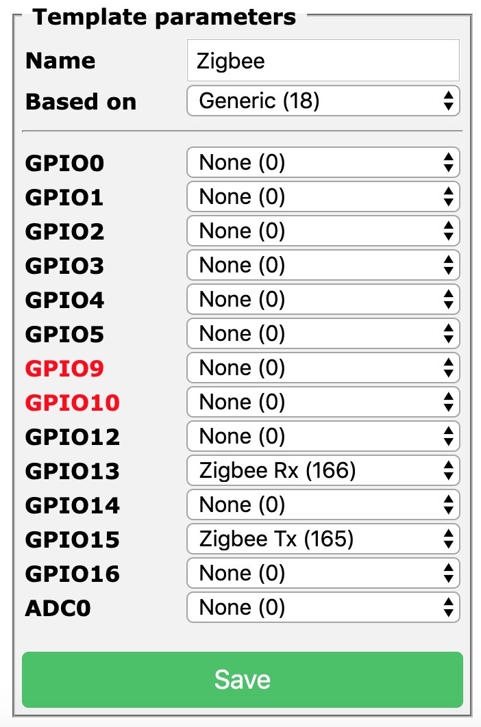
Configure the Tasmota device using a custom template. Assign Zigbee Tx (165) and Zigbee Rx (166) to the corresponding GPIOs to be used for serial communication with the CC2530. For example:
{"NAME":"Zigbee","GPIO":[0,0,0,0,0,0,0,0,0,166,0,165,0],"FLAG":0,"BASE":18}
Due to memory constraints of the CC2530, you can only pair 16 devices to a coordinator (See details).
There is an alternative firmware allowing for Zigbee routers to create a mesh network and go beyond 16 devices. This is currently not tested nor supported by Zigbee2Tasmota. It may be added later.
Zigbee2Tasmota is still in its early phase. Logging is set to verbose mode to ease reporting or debugging. It should become less verbose in the future.
After the Tasmota device boots, Zigbee2Tasmota will wait for 15 seconds before initializing the CC2530. This time allows for Wi-Fi and MQTT connection (hopefully).
When you first run your CC2530, you will see additional steps to configure the device:
MQT: tele/<topic>/RESULT = {"ZigbeeZNPSent":"410000"}
MQT: tele/<topic>/RESULT = {"ZigbeeZNPReceived":"4180020200020603"}
MQT: tele/<topic>/RESULT = {"ZigbeeState":{"Status":1,"Message":"CC2530 booted","RestartReason":"Watchdog","MajorRel":2,"MinorRel":6}}
ZIG: checking device configuration
MQT: tele/<topic>/RESULT = {"ZigbeeZNPSent":"2108000F00"}
MQT: tele/<topic>/RESULT = {"ZigbeeZNPReceived":"61080200"}
MQT: tele/<topic>/RESULT = {"ZigbeeState":{"Status":2,"Message":"Reseting configuration"}}
MQT: tele/<topic>/RESULT = {"ZigbeeZNPSent":"2605030102"}
MQT: tele/<topic>/RESULT = {"ZigbeeZNPReceived":"660500"}
MQT: tele/<topic>/RESULT = {"ZigbeeZNPSent":"410000"}
MQT: tele/<topic>/RESULT = {"ZigbeeZNPReceived":"4180020200020603"}
MQT: tele/<topic>/RESULT = {"ZigbeeZNPSent":"26058302631A"}
MQT: tele/<topic>/RESULT = {"ZigbeeZNPReceived":"660500"}
MQT: tele/<topic>/RESULT = {"ZigbeeZNPSent":"26052D08CCCCCCCCCCCCCCCC"}
MQT: tele/<topic>/RESULT = {"ZigbeeZNPReceived":"660500"}
MQT: tele/<topic>/RESULT = {"ZigbeeZNPSent":"2605840400080000"}
MQT: tele/<topic>/RESULT = {"ZigbeeZNPReceived":"660500"}
MQT: tele/<topic>/RESULT = {"ZigbeeZNPSent":"2605870100"}
MQT: tele/<topic>/RESULT = {"ZigbeeZNPReceived":"660500"}
MQT: tele/<topic>/RESULT = {"ZigbeeZNPSent":"2605621001030507090B0D0F00020406080A0C0D"}
MQT: tele/<topic>/RESULT = {"ZigbeeZNPReceived":"660500"}
MQT: tele/<topic>/RESULT = {"ZigbeeZNPSent":"2605630100"}
MQT: tele/<topic>/RESULT = {"ZigbeeZNPReceived":"660500"}
MQT: tele/<topic>/RESULT = {"ZigbeeZNPSent":"210901010020FFFFFFFFFFFFFFFF5A6967426565416C6C69616E636530390000000000000000"}
MQT: tele/<topic>/RESULT = {"ZigbeeZNPReceived":"610900"}
MQT: tele/<topic>/RESULT = {"ZigbeeZNPSent":"26058F0101"}
MQT: tele/<topic>/RESULT = {"ZigbeeZNPReceived":"660500"}
MQT: tele/<topic>/RESULT = {"ZigbeeZNPSent":"2107000F01000100"}
MQT: tele/<topic>/RESULT = {"ZigbeeZNPReceived":"610709"}
MQT: tele/<topic>/RESULT = {"ZigbeeZNPSent":"2109000F000155"}
MQT: tele/<topic>/RESULT = {"ZigbeeZNPReceived":"610900"}
MQT: tele/<topic>/RESULT = {"ZigbeeState":{"Status":3,"Message":"Configured, starting coordinator"}}
MQT: tele/<topic>/RESULT = {"ZigbeeZNPSent":"25406400"}
MQT: tele/<topic>/RESULT = {"ZigbeeZNPReceived":"654001"}
MQT: tele/<topic>/RESULT = {"ZigbeeZNPReceived":"45C008"}
MQT: tele/<topic>/RESULT = {"ZigbeeZNPReceived":"45C008"}
MQT: tele/<topic>/RESULT = {"ZigbeeZNPReceived":"45C008"}
MQT: tele/<topic>/RESULT = {"ZigbeeZNPReceived":"45C008"}
MQT: tele/<topic>/RESULT = {"ZigbeeZNPReceived":"45C009"}
MQT: tele/<topic>/RESULT = {"ZigbeeZNPSent":"2700"}
MQT: tele/<topic>/RESULT = {"ZigbeeZNPReceived":"6700006FF09D19004B12000000070900"}
MQT: tele/<topic>/RESULT = {"ZigbeeState":{"Status":51,"IEEEAddr":"00124B00199DF06F","ShortAddr":"0x0000","DeviceType":7,"DeviceState":9,"NumAssocDevices":0}}
MQT: tele/<topic>/RESULT = {"ZigbeeZNPSent":"250200000000"}
MQT: tele/<topic>/RESULT = {"ZigbeeZNPReceived":"650200"}
MQT: tele/<topic>/RESULT = {"ZigbeeZNPReceived":"4582000000000000408F000050A0000100A00000"}
MQT: tele/<topic>/RESULT = {"ZigbeeZNPSent":"250500000000"}
MQT: tele/<topic>/RESULT = {"ZigbeeZNPReceived":"650500"}
MQT: tele/<topic>/RESULT = {"ZigbeeZNPReceived":"4585000000000000"}
MQT: tele/<topic>/RESULT = {"ZigbeeZNPSent":"2400010401050000000000"}
MQT: tele/<topic>/RESULT = {"ZigbeeZNPReceived":"640000"}
MQT: tele/<topic>/RESULT = {"ZigbeeZNPSent":"24000B0401050000000000"}
MQT: tele/<topic>/RESULT = {"ZigbeeZNPReceived":"640000"}
MQT: tele/<topic>/RESULT = {"ZigbeeZNPSent":"250500000000"}
MQT: tele/<topic>/RESULT = {"ZigbeeZNPReceived":"650500"}
MQT: tele/<topic>/RESULT = {"ZigbeeZNPReceived":"45850000000000020B01"}
MQT: tele/<topic>/RESULT = {"ZigbeeZNPSent":"25360200000000"}
MQT: tele/<topic>/RESULT = {"ZigbeeZNPReceived":"653600"}
MQT: tele/<topic>/RESULT = {"ZigbeeZNPReceived":"45CB00"}
MQT: tele/<topic>/RESULT = {"ZigbeeZNPReceived":"45B6000000"}
MQT: tele/<topic>/RESULT = {"ZigbeeState":{"Status":0,"Message":"Started"}}
ZIG: zigbee device ready, listening...
You can also force a complete reconfiguration of your CC2530 with the following command, and reboot:
ZigbeeZNPSend 2112000F0100
Normal boot looks like:
MQT: tele/<topic>/INFO3 = {"RestartReason":"External System"}
MQT: tele/<topic>/RESULT = {"ZigbeeZNPSent":"410000"}
MQT: tele/<topic>/RESULT = {"ZigbeeZNPReceived":"4180020200020603"}
MQT: tele/<topic>/RESULT = {"ZigbeeState":{"Status":1,"Message":"CC2530 booted","RestartReason":"Watchdog","MajorRel":2,"MinorRel":6}}
ZIG: checking device configuration
MQT: tele/<topic>/RESULT = {"ZigbeeZNPSent":"2108000F00"}
MQT: tele/<topic>/RESULT = {"ZigbeeZNPReceived":"6108000155"}
MQT: tele/<topic>/RESULT = {"ZigbeeZNPSent":"2102"}
MQT: tele/<topic>/RESULT = {"ZigbeeZNPReceived":"61020200020603901534010200000000"}
MQT: tele/<topic>/RESULT = {"ZigbeeState":{"Status":50,"MajorRel":2,"MinorRel":6,"MaintRel":3,"Revision":20190608}}
MQT: tele/<topic>/RESULT = {"ZigbeeZNPSent":"260483"}
MQT: tele/<topic>/RESULT = {"ZigbeeZNPReceived":"6604008302631A"}
MQT: tele/<topic>/RESULT = {"ZigbeeZNPSent":"26042D"}
MQT: tele/<topic>/RESULT = {"ZigbeeZNPReceived":"6604002D08CCCCCCCCCCCCCCCC"}
MQT: tele/<topic>/RESULT = {"ZigbeeZNPSent":"260484"}
MQT: tele/<topic>/RESULT = {"ZigbeeZNPReceived":"660400840400080000"}
MQT: tele/<topic>/RESULT = {"ZigbeeZNPSent":"260462"}
MQT: tele/<topic>/RESULT = {"ZigbeeZNPReceived":"660400621001030507090B0D0F00020406080A0C0D"}
MQT: tele/<topic>/RESULT = {"ZigbeeZNPSent":"260463"}
MQT: tele/<topic>/RESULT = {"ZigbeeZNPReceived":"660400630100"}
MQT: tele/<topic>/RESULT = {"ZigbeeState":{"Status":3,"Message":"Configured, starting coordinator"}}
MQT: tele/<topic>/RESULT = {"ZigbeeZNPSent":"25406400"}
MQT: tele/<topic>/RESULT = {"ZigbeeZNPReceived":"654000"}
MQT: tele/<topic>/RESULT = {"ZigbeeZNPReceived":"45C009"}
MQT: tele/<topic>/RESULT = {"ZigbeeZNPSent":"2700"}
MQT: tele/<topic>/RESULT = {"ZigbeeZNPReceived":"6700006FF09D19004B12000000070901208F"}
MQT: tele/<topic>/RESULT = {"ZigbeeState":{"Status":51,"IEEEAddr":"00124B00199DF06F","ShortAddr":"0x0000","DeviceType":7,"DeviceState":9,"NumAssocDevices":1,"AssocDevicesList":["0x8F20"]}}
MQT: tele/<topic>/RESULT = {"ZigbeeZNPSent":"250200000000"}
MQT: tele/<topic>/RESULT = {"ZigbeeZNPReceived":"650200"}
MQT: tele/<topic>/RESULT = {"ZigbeeZNPReceived":"4582000000000000408F000050A0000100A00000"}
MQT: tele/<topic>/RESULT = {"ZigbeeZNPSent":"250500000000"}
MQT: tele/<topic>/RESULT = {"ZigbeeZNPReceived":"650500"}
MQT: tele/<topic>/RESULT = {"ZigbeeZNPReceived":"4585000000000000"}
MQT: tele/<topic>/RESULT = {"ZigbeeZNPSent":"2400010401050000000000"}
MQT: tele/<topic>/RESULT = {"ZigbeeZNPReceived":"640000"}
MQT: tele/<topic>/RESULT = {"ZigbeeZNPSent":"24000B0401050000000000"}
MQT: tele/<topic>/RESULT = {"ZigbeeZNPReceived":"640000"}
MQT: tele/<topic>/RESULT = {"ZigbeeZNPSent":"250500000000"}
MQT: tele/<topic>/RESULT = {"ZigbeeZNPReceived":"650500"}
MQT: tele/<topic>/RESULT = {"ZigbeeZNPReceived":"45850000000000020B01"}
MQT: tele/<topic>/RESULT = {"ZigbeeZNPSent":"25360200000000"}
MQT: tele/<topic>/RESULT = {"ZigbeeZNPReceived":"653600"}
MQT: tele/<topic>/RESULT = {"ZigbeeZNPReceived":"45CB00"}
MQT: tele/<topic>/RESULT = {"ZigbeeZNPReceived":"45B6000000"}
MQT: tele/<topic>/RESULT = {"ZigbeeState":{"Status":0,"Message":"Started"}}
ZIG: Zigbee started
For a list of available command see Zigbee Commands.
Note
Zigbee will automatically boot the CC2530 device, configure it and wait for Zigbee messages.
You can inspect the log output to determine whether Zigbee2Tasmota started correctly. Zigbee2Tasmota sends several status messages to inform the MQTT host about initialization.
Ex: {"ZigbeeState":{"Status":1,"Message":"CC2530 booted","RestartReason":"Watchdog","MajorRel":2,"MinorRel":6}}
Statuscontains a numeric code about the status message0: initialization complete, Zigbee2Tasmota is running normally1: booting2: resetting CC2530 configuration3: starting Zigbee coordinator20: disabling Permit Join21: allowing Permit Join for 60 seconds22: allowing Permit Join until next boot30: Zigbee device connects or reconnects31: Received Node Descriptor information for a Zigbee device32: Received the list of active endpoints for a Zigbee device33: Received the simple Descriptor with active ZCL clusters for a Zigbee device50: reporting CC2530 firmware version51: reporting CC2530 device information and associated devices98: error, unsupported CC2530 firmware99: general error, Zigbee2Tasmota was unable to start
Message(optional) a human-readable message- other fields depending on the message (e.g., Status=
50or Status=51)
By default, and for security reasons, the Zigbee coordinator does not automatically accept new devices. To pair new devices, use ZigbeePermitJoin 1. Once Zigbee2Tasmota is in pairing mode, put the Zigbee device into pairing mode. This is usually accomplished by pressing the button on the device for 5 seconds or more. To stop pairing, use ZigbeePermitJoin 0.
Sensor messages are published via MQTT when they are received from the Zigbee device. Unlike Zigbee2MQTT, there is currently no debouncing nor caching.
Example for Aqara Temperature & Humidity Sensor

This sensor monitors humidity, temperature, and air pressure. Its Zigbee model ID is lumi.weather.
- Put Zigbee2Tasmota into pairing mode using the
ZigbeePermitJoincommand as described above - Press the Xiaomi Aqara sensor's button for 5 seconds to pair the devices. You will see a message as follows:
MQT: tele/<topic>/RESULT = {"ZigbeeState":{"Status":30,"IEEEAddr":"00158D00036B50AE","ShortAddr":"0x8F20","PowerSource":false,"ReceiveWhenIdle":false,"Security":false}}
| Field name | Value |
|---|---|
Status |
30 indicates a device connect or reconnect. This is the opportunity to match IEEEAddress and short address |
IEEEAddr |
Long unique address (64 bits) of the device - factory set |
ShortAddr |
Short address (16 bits) randomly assigned to the device on this Zigbee network |
PowerSource |
true = the device is connected to a power sourcefalse = the device runs on battery |
ReceiveWhenIdle |
true = the device can receive commands when idlefalse = the device is not listening. Commands should be sent when the device reconnects and is idle |
Security |
Security capability (meaning unknown, to be determined) |
This device publishes sensor values roughly every hour or when a change occurs. You can also force an update pressing the device's button. It sends two kinds of messages, either 3x standard Zigbee messages, or a single proprietary message containing all sensor values.
Examples:
MQT: tele/<topic>/RESULT = {"0x8F20":{"Humidity":23.47}}
MQT: tele/<topic>/RESULT = {"0x8F20":{"Temperature":59.85}}
MQT: tele/<topic>/RESULT = {"0x8F20":{"Pressure":1005,"PressureUnit":"hPa"}}
MQT: tele/<topic>/RESULT = {"0x8F20":{"Temperature":23.47,"Humidity":58.97,"Pressure":1005.8,"PressureUnit":"hPa","Voltage":3.005,"Battery":100}}
MQT: tele/<topic>/RESULT = {"0x8F20":{"ModelId":"lumi.weather"}}
0x8F20 is the ShortAddress of the sensor.
Supported values:
| Field name | Value |
|---|---|
Humidity |
Humidity in percentage (float) |
Pressure and PressureUnit |
Atmospheric pressure (float) and unit (string) Currently only hPa (A.K.A. mbar) is supported |
Temperature |
Temperature in Celsius (float) |
Voltage |
Battery voltage (float) |
Battery |
Battery charge in percentage (integer) |
ModelId |
Model name of the Zigbee device (string) Ex: lumi.weather |
You can dump the internal information gathered about connected Zigbee devices with the command ZigbeeStatus.
ZigbeeStatus1 - List all connected devices
{"ZigbeeStatus-99":[{"ShortAddr":"0x6B58"},{"ShortAddr":"0xE9C3"},{"ShortAddr":"0x3D82"}]}(JSON pretty-printed for readability)
{
    "ZigbeeStatus-99": [
        {
            "ShortAddr":"0x6B58"
        },
        {
            "ShortAddr":"0xE9C3"
        },
        {
            "ShortAddr":"0x3D82"
        }
    ]
}
ZigbeeStatus 2 - Display detailed information for each device, including long address, model and manufacturer:
{"ZigbeeStatus2":[{"ShortAddr":"0x6B58","IEEEAddr":"7CB03EAA0A0292DD","ModelId":"Plug 01","Manufacturer":"OSRAM"},{"ShortAddr":"0xE9C3","IEEEAddr":"00158D00036B50AE","ModelId":"lumi.weather","Manufacturer":"LUMI"},{"ShortAddr":"0x3D82","IEEEAddr":"0017880102FE1DBD","ModelId":"LWB010","Manufacturer":"Philips"}]}(formatted for readability)
{
    "ZigbeeStatus2": [
        {
            "ShortAddr": "0x6B58",
            "IEEEAddr": "7CB03EAA0A0292DD",
            "ModelId": "Plug 01",
            "Manufacturer": "OSRAM"
        },
        {
            "ShortAddr": "0xE9C3",
            "IEEEAddr": "00158D00036B50AE",
            "ModelId": "lumi.weather",
            "Manufacturer": "LUMI"
        },
        {
            "ShortAddr": "0x3D82",
            "IEEEAddr": "0017880102FE1DBD",
            "ModelId": "LWB010",
            "Manufacturer": "Philips"
        }
    ]
}You can use ZigbeeStatus3 to display information about all the endpoints and ZCL clusters supported. If probing was successful (at pairing time or using ZigbeeProbe), Tasmota will automatically find the right endpoint. If the device was not probed, you need to specify the endpoint explicitly. It is always better to explicitly add the endpoint number if you know it.
| Device | Endpoint |
|---|---|
| OSRAM Plug | 0x03 |
| Philips Hue Bulb | 0x0B |
{"ZigbeeStatus3":[{"ShortAddr":"0x6B58","Endpoints":{"0x03":{"ProfileId":"0xC05E","ProfileIdName":"ZigBee Light Link","ClustersIn":["0x1000","0x0000","0x0003","0x0004","0x0005","0x0006","0x0B04","0xFC0F"],"ClustersOut":["0x0019"]}}},{"ShortAddr":"0xE9C3","Endpoints":{"0x01":{"ProfileId":"0x0104","ClustersIn":["0x0000","0x0003","0xFFFF","0x0402","0x0403","0x0405"],"ClustersOut":["0x0000","0x0004","0xFFFF"]}}},{"ShortAddr":"0x3D82","Endpoints":{"0x0B":{"ProfileId":"0xC05E"," ...(formatted for readability)
{
  "ZigbeeStatus3": [
    {
      "ShortAddr": "0x6B58",
      "Endpoints": {
        "0x03": {
          "ProfileId": "0xC05E",
          "ProfileIdName": "ZigBee Light Link",
          "ClustersIn": [
            "0x1000",
            "0x0000",
            "0x0003",
            "0x0004",
            "0x0005",
            "0x0006",
            "0x0B04",
            "0xFC0F"
          ],
          "ClustersOut": [
            "0x0019"
          ]
        }
      }
    },
    {
      "ShortAddr": "0xE9C3",
      "Endpoints": {
        "0x01": {
          "ProfileId": "0x0104",
          "ClustersIn": [
            "0x0000",
            "0x0003",
            "0xFFFF",
            "0x0402",
            "0x0403",
            "0x0405"
          ],
          "ClustersOut": [
            "0x0000",
            "0x0004",
            "0xFFFF"
          ]
        }
      }
    },
    {
      "ShortAddr": "0x3D82",
      "Endpoints": {
        "0x0B": {
          "ProfileId": "0xC05E",
          " ...
        }
      }
    }
  ]
}
[!EXAMPLE] OSRAM Zigbee plug
{"Device":"0x69CF","IEEEAddr":"0000000000000000","ModelId":"Plug 01","Manufacturer":"OSRAM","Endpoints":{"0x03":{"ProfileId":"0xC05E","ProfileIdName":"ZigBee Light Link","ClustersIn":["0x1000","0x0000","0x0003","0x0004","0x0005","0x0006","0x0B04","0xFC0F"],"ClustersOut":["0x0019"]}}}The message above shows that the device supports only one endpoint 0x03 which accepts messages (ClustersIn) for clusters "0x1000","0x0000","0x0003","0x0004","0x0005","0x0006","0x0B04","0xFC0F".
| Command | Parameters | Cluster |
|---|---|---|
| Power | 1|true|"true"|"on": On0|false|"false"|"off": Off2|"Toggle": Toggle |
0x0006 |
| Dimmer | 0..254: Dimmer value255 is normally considered as invalid, and may be converted to 254 |
0x0008 |
| Dimmer+ | null: no parameter. Increases dimmer by 10% |
0x0008 |
| Dimmer- | null: no parameter. Decreases dimmer by 10% |
0x0008 |
| DimmerStop | null: no parameter. Stops any running increase of decrease of dimmer. |
0x0008 |
| ResetAlarm | <alarmcode>,<clusterid>: (to be documented later) |
0x0009 |
| ResetAllAlarms | null: no parameter, (to be documented later) |
0x0009 |
| Hue | 0..254: change Hue value |
0x0300 |
| Sat | 0..254: change Sat value |
0x0300 |
| HueSat | 0..254,0..254: change both Hue and Sat values |
0x0300 |
| Color | 0..65534,0..65534: change the color using [x,y] coordinates |
0x0300 |
| CT | 0..65534: change the white color-temperature in Mireds |
0x0300 |
| Shutter | 0..254: send any Shutter command (prefer the commands below) |
0x0102 |
| ShutterOpen | null: no parameter, open shutter |
0x0102 |
| ShutterClose | null: no parameter, close shutter |
0x0102 |
| ShutterStop | null: no parameter, stop shutter movement |
0x0102 |
| ShutterLift | 0..100: move shutter to a specific position in percent0%=open, 100%=closed |
0x0102 |
| ShutterTilt | 0..100: move the shutter to the specific tilt position in percent |
0x0102 |
Examples:
ZigbeeSend { "device":"0x69CF", "endpoint":"0x03", "send":{"Power":"On"} }
ZigbeeSend { "device":"0x69CF", "endpoint":"0x03", "send":{"Power":1} }
ZigbeeSend { "device":"0x69CF", "endpoint":"0x03", "send":{"Power":false} }
ZigbeeSend { "device":"0x69CF", "endpoint":"0x03", "send":{"Power":"Toggle"} }
Read the On/Off status: (all three commands below are synonyms)
ZigbeeRead { "device":"0x69CF", "endpoint":"0x03", "cluster":"0x0006", "read":"0x0000" }
ZigbeeRead { "device":"0x69CF", "endpoint":"0x03", "cluster":"0x0006", "read":["0x0000"] }
ZigbeeRead { "device":"0x69CF", "endpoint":3, "cluster":6, "read":0 }ZigbeeSend { "device":"0x3D82", "endpoint":"0x0B", "send":{"Power":"Off"} }
ZigbeeSend { "device":"0x3D82", "endpoint":"0x0B", "send":{"Dimmer":128} }
ZigbeeSend { "device":"0x3D82", "endpoint":"0x0B", "send":{"Dimmer":254} }
ZigbeeSend { "device":"0x3D82", "endpoint":"0x0B", "send":{"Dimmer":0} }There are several excellent open-source Zigbee to MQTT solutions like the widely used Zigbee2mqtt or Aqara Hub. Zigbee2mqtt is a comprehensive solution but requires at least a Raspberry Pi to run it. Zigbee2Tasmota is a lightweight solution running on an ESP82xx Wi-Fi chip. Hence it is easier to deploy in your living room or around your home.