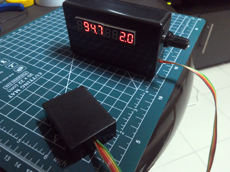
This is a multipurpose tool meant to aid in the use of telescopes, it features:
- Zeroable Compass (not tilt compensated), with 0.1 degree resolution. Stores offset to EEPROM.
- Zeroable Clinometer with 0.1 degree resolution. Stores offset to EEPROM.
- Zeroable 2 axis digital Level with 0.1 degree resolution. Stores offsets to EEPROM.
- Brightness control.
These can be useful for leveling a telescope and for doing basic polar alignment, or as a very simple alt-azimuth display of telescope position.
Here is a 6 minute youtube video describing how it works:
- Arduino Mega328 development board (UNO, Pro or similar). The one in the video is a Pro mini 5V 16Mhz
- HMC5883 sensor module, I used the GY-271 variant.
- MMA8452 accelerometer, I used the GY-45 variant.
- 7 Segment, 8 Digit, MAX72XX controlled, 5 Wire LED display.
- KY-040 Rotary encoder, for user input (selecting mode, zeroing the compass and inclinometer, adjusting display brightness)
- SDA = A4 (4.7K pullup to VCC recommended)
- SCL = A5 (4.7K pullup to VCC recommended)
- SDA, SCL and GND: matching the Arduino
- VCC (from Arduino) to VCC_IN, not to the 3V3 pin
- SAO (address select) to GND.
- When used as a digital level, the accelerometer is meant to be used horizontal (Z axis pointing to the sky).
- When used as inclinometer or DSC, the acelerometer is meant to be used vertical, with the Z axis pointing to the horizon.
- SDA, SCL, VCC and GND: matching the Arduino
- DRDY pin disconnected
- The HMC5883 is meant to be used on a permanently horizontal position (not attached to the telescope tube)
- VCC and GND: matching the Arduino
- DIN (Data In) connected to Arduino pin 12
- CLK connected to Arduino pin 11
- LOAD (CS) connected to Arduino pin 10
- CLK connected to Arduino pin 2
- DT connected to Arduino pin 3
- SW connected to Arduino pin 4, and through a 10K pullup to VCC.
- VCC (sometimes labeled "+") connected to Arduino VCC
- GND connected to Arduino GND
