-
Notifications
You must be signed in to change notification settings - Fork 83
Basic Troubleshooting
These are some basic problems. For anything not covered here, go to the HeaterMeter online community on The Virtual Weber Bulletin Board tvwbb.com. For most troubleshooting, using the rPi USB power input is preferred in order to avoid the chance of subjecting the rPi to 12V which will definitely fry components on it.
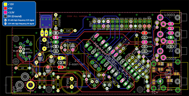
HeaterMeter v4.2 Voltages / Board / Schematics (assumes microcontroller is operational)
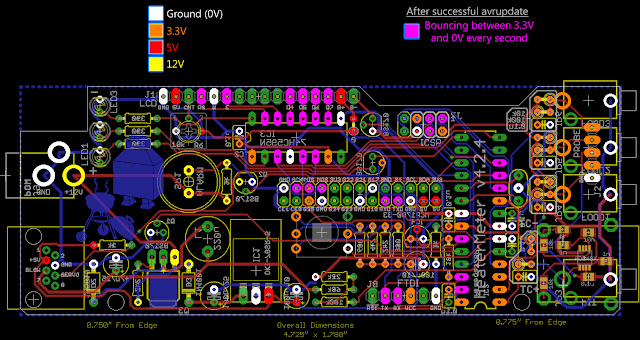
HeaterMeter v4.3 Voltages / Board / Schematics (assumes microcontroller is operational)

- Start by ensuring you can connect to openwrt on your Raspberry Pi see [HeaterMeter 4.x Software](HeaterMeter 4.x Software#configuration)
- If you can connect to the Raspberry Pi, look at the system log (Configuration -> Status -> System Log) to see if your heatermeter was recognized.
- Verify that all necessary components are on the board and in the right place.
- Ensure sure you pushed solder through on every connection so that a connection is made on both sides of the board.
You can't have both the wired and wireless adapters on the same subnet. Even worse, DHCP sets the wired ethernet as the gateway for the wireless which means the wireless can't talk unless the wired is plugged in.
Some people have had success by ensuring the wired interface does not start at boot (go to the advanced tab of the LAN and uncheck the auto start option and reboot the device) * This is risky if you configure the wifi configuration wrong and don't have a usb keyboard and hdmi output in order to recover.
Set the names of all three probes to override weird characters. Mine are creatively named "Probe 1", "Probe 2", and "Probe 3".
In AVR firmware 20190327B and above, HeaterMeter contains a set of diagnostics to help troubleshoot probe issues. From the HeaterMeter device LCD, navigate into the menus to the "Manual fan mode Yes/No" menu and hold the left button to enter the diagnostics hidden menu. Use left and right buttons to navigate between displays in the diagnostics menu and hold left button to exit. Using the diagnostic menus can be done at any time and does not affect the HeaterMeter operation.
P0 ADB01744 01Nz
Kcouple  74.47*F
- Line 1
- Probe Number (P0 through P3)
- Raw oversampled/decimated ADC reading (14-bit, 16383 max). If the reading begins with
ADC, then the reading is using AVCC as the reference voltage, so the voltage isX / 16383 * 3.3V. If the reading begins withADB, then the reading is using the internal bandgap reference voltage of approximately 1.1V so the voltage is approximatelyX / 16383 * 1.1V. To get the true voltage reading, the bandgap reference measurement must be calculated, see below. - Noise. The noise calculation indicates how stable the reading was during a 256 sample ~20ms measurement period. The value shown here is divided by 4. Normal stable values are 00-01, 02-03 is considered noisy, 04+ is probably unusable.
- Line 2
- Probe type
- KCouple - Analog Type K Thermocouple
- Thermis - Analog Thermistor (Thermoworks Pro-Series, Maverick probe, etc)
- RfWirel - RFM12B 915MHz wireless probe
- Disable - Disabled
- Current calculated temperature and units to two decimal places
- Probe type
Fan228=121V 00Nz
Btn000=0   BG342
- Line 1
- Blower feedback ADC (8-bit, 255 max). The raw ADC reading of the output voltage of the buck (step-down) converter. To convert to voltage at the AVR,
X / 255 * 3.3V - Blower feedback voltage (in decivolts). The calculated blower voltage being output on the blower pin corresponding to the ADC reading. Values should range from 050V (5.0V) to 121V (12.1V) when a blower is plugged in.
- Noise in the blower feedback circuit. Same as with the probes, this number is the noise divided by 4. There is intrinsically a lot of ripple on the blower output so higher values are ok, probably up to 09 is perfectly acceptable. Larger blowers will see a higher value here.
- Blower feedback ADC (8-bit, 255 max). The raw ADC reading of the output voltage of the buck (step-down) converter. To convert to voltage at the AVR,
- Line 2
- Button ADC (8-bit, 255 max). The raw ADC reading of the button input. This should be 000 while no button is being pressed.
- Detected button. If a button is being pressed, it should display here.
- 0 - No button detected
- 1 - Left
- 2 - Right
- 4 - Up
- 8 - Down
- Bandgap reference scale (10-bit, 1023 max). HeaterMeter measures the bandgap reference (~1.1V) against AVCC and uses that value to measure the voltage of thermocouples less than ~430F. To calculate the exact bandgap reference voltage, which varies per chip and dependent on the temperature, measure your 3.3V voltage at the AVC pin on the microcontroller and multiply that by this scale
X / 1023 * 3.3V. Example: BG342, 3.297V measured voltage,342 / 1023 * 3.297V = 1.102V. Use this exact voltage instead of 1.1V when calculating any probe's voltage from anADBreading above.

