About Jarvis
Update: We're on Hack a Day. If you found this interesting, check out our website.
Jarvis is the system we have designed to control the door at our hackerspace.
The system has four main parts:
- A computer
- An RFID reader
- A remote
- An electric door lock (duh)
The door has an electric lock which is wirelessly controlled by a computer using XBee modules for the wireless communication. The software running on our computer (Jarvis) is responsible for handling the calls to open the door, and controls the door lock appropriately.
We currently open the door when someone uses their valid RFID tag on the reader, and when someone uses the door remote (more on that later).
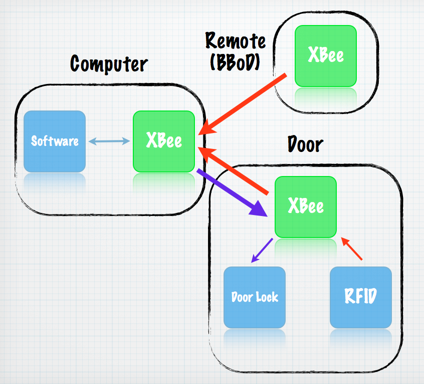 Overview of our system
For the computer:
- 1 x XBee Series 1 module
- 1 x XBee Explorer USB
For the remote:
- 1 x XBee Series 1 module
- 4 x AA Alkaline Batteries
- 1 x AA battery holder
- 1 x Mushroom Button (any button will do)
- 1 x project box
For the door controller:
- 1 x XBee Series 1 module
- 1 x RFID reader (we used the ID-20 model from Sparkfun)
- 1 x XBee Explorer Regulated
- 1 x NPN Transistor (like 2N2222A or 2N3904)
- 1 x 1N4148 Diode
- 1 x 1KOhm resistor
- 1 x 10KOhm resistor
- 1 x 1KOhm resistor and LED (optional)
- some kind of casing
And last but not least, you will need an electric door lock, and possibly a transformer for that. We bought an ultra awesome (read: expensive) door lock from CISA which required a 2A@12V AC transformer to power it.
The XBee modules implement the 802.15.4 low-power protocol for communication. The main reasons we use them are:
- They are very popular in the hobbyist and Arduino communities.
- They support I/O line passthrough
- They support Serial (Rx/Tx) passthrough
The XBee modules have 8 Digital Input/Output (DIO) pins. The awesome thing about them is that you can set a pin, i.e. pin D0 on an XBee (let's call it XBee1) as an input, the status of which will be continuously broadcast to another XBee, Xbee2. If you also set D0 of XBee2 as an output, then XBee1's D0 pin status will control XBee2's D0 pin status! Therefore, if XBee1's D0 status is set to LOW, XBee2's D0 will change to LOW as well!
Serial passthrough is the killer feature of the XBee modules. Serial interfaces consist of at least two pins, Tx (transmit) and Rx (receive). For two devices to talk to each other using a serial interface, you need to connect the first device's Tx pin to the second device's Rx pin and vice versa. XBees are connected to the computer and other devices (like the Arduino) by a serial interface.
What the XBee actually does is take the data it receives, and broadcast it to all nearby XBee modules. When a module receives data, they send it through their transmit pin to their device. This way, an Arduino and a computer can talk to each other through their serial ports, and their data is wirelessly passed through by the XBee.
The circuit that controls the electric door lock is a fairly simple one. First of all, the electric door's operation is as dumb as it gets. When it is powered, the door unlocks. We are taking advantage of the I/O line passthrough features of the XBee to control a relay which powers the electric door lock, hence opening the door. We have simply attached the DTR serial pin of the computer to pin D0 of the XBee connected to the computer, and attached a relay control circuit (there is an excellent Sparkfun tutorial on that) at pin D0 of the XBee on the door. We have set the DTR pin to LOW by default, and when we want to open the door, we set it to HIGH (5V) for two seconds, (which is more than sufficient for the door to unlock), and then back to LOW. When the D0 pin of the computer's XBee is set to HIGH, the D0 pin of the door's XBee is also set to HIGH, which in turn controls the relay, which powers the door lock, and the door unlocks.
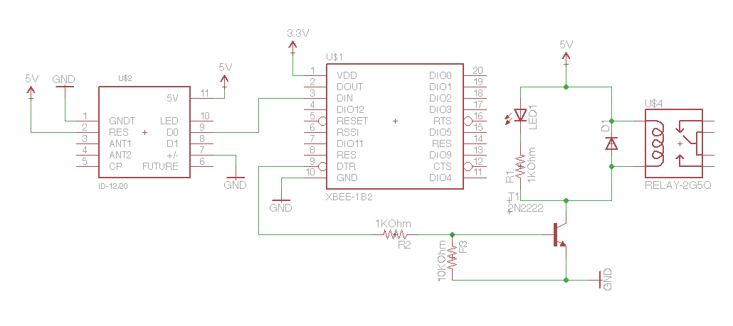 Schematic for the Controller. Notice the XBee, the RFID reader and the control circuit for the door lock.
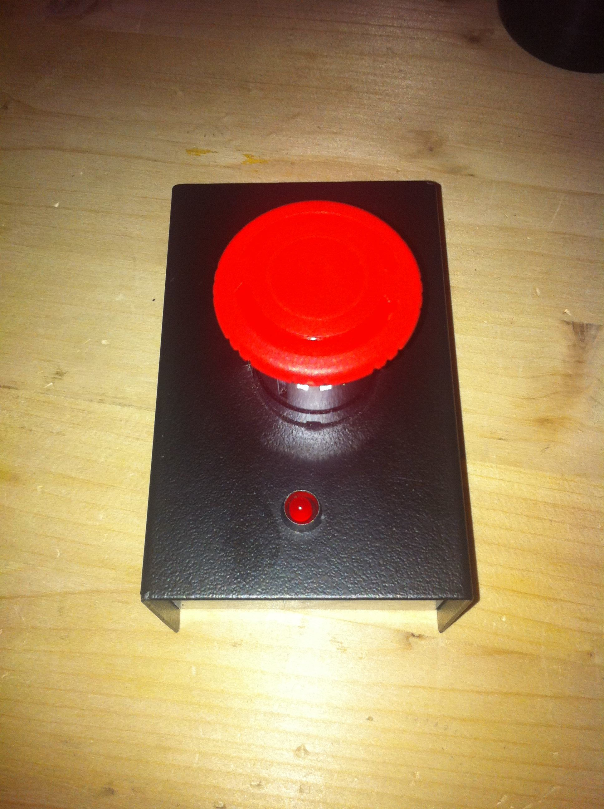 BBoDWe wanted to be able to open the door using a remote, when someone rings our doorbell and somebody is inside. To achieve that, we are using yet another XBee module powered by batteries, with a huge mushroom-type button acting as the circuit power switch. The XBee is configured to automatically send commands to the computer when powered on, so when we press the button and the XBee is powered, the software at the computer intercepts the incoming data and opens the door. We call our remote Big Button of Doom
This design is good for a number of reasons, the most important of which is power consumption. Since the XBee module is only powered while we are pressing the button, it consumes power for less than a minute per day. This allows us to run it on two plain alkaline AA batteries for up to a year! Having only an XBee, a button and a battery (ok, and an LED tbh) in the circuit also helps keep the cost down. ;)
Instead of keys, we are using RFID tags for our hackerspace. Each member has their own RFID tag, and they can enter the space any time they want. When an RFID tag comes close to the RFID reader, the ID of the card is read, and sent out through a serial communication port. We use the XBee's serial passthrough to send the data from the RFID reader to the computer. We have connected the RFID reader's Tx pin to the door XBee's Rx pin which communicates them to the XBee on the computer and therefore, the ID of the card is wirelessly sent to the computer via the XBee modules. The software we have built simply reads the card's ID, checks if they are valid by looking into a plaintext file which contains a list of valid card IDs and their owners, and unlocks the door if the card is valid (see Door controller).