-
Notifications
You must be signed in to change notification settings - Fork 1
1. Testing the components involved.
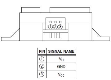
Interfacing the Sharp IR 2Y0A21 with the Arduino is very simple! The pins from the module are as follows:
Connections:
Vo <---> Arduino Analog Pin (A0)
Vcc <---> 5V
GND <---> GND
The Vo pin from the sensor gives analog values between roughly 0.4V to 2.6V for distances ranging 80cm to 10cm (Voltage decreases as distance increases). So by reading these analog values from Vo pin, we can directly relate it to the distance!
This library here by guillaume-rico makes the job even simpler for us. Get his library and check out his example code.
To make a standalone system we'll be powering the Arduino using 2 single cell(1s) Lipos in series as the Arduino Nano Specs recommend 7-12V for the Vin pin.
The servo motor SG90 is a tiny 9g servo. So it doesn't draw much current(as compared to larger servos) and can be directly supplied from the Arduino 5V pin, for now(In the modules, it is drawn from the LiPos after being regulated to 5-6V). MG90S is also a micro servo but with metal gears instead of nylon gears as in the SG90. Ideally, you would use a separate 5V power supply for the servos but here we source it from the Arduino. So if you face some funky behaviour, switch to an external supply.
Connect a single servo to your Arduino pin D9, along with 5V and GND, and load up the Arduino example code under Servo>Sweep. That should test your servos.
There are lots of tutorials available online for this step and these may vary slightly based on the type of module you have. Firstly, try connecting a single HC05 to your Smartphone Bluetooth and use an app such as 'Bluetooth Terminal' on your phone to see if your module works as expected. Try different baud rates (Usually 9600 or 38400) on the HC05 side. Make sure you have 'Both NL & CR' selected while sending data from HC05.
After that, try pairing 2 HC05 modules with each other in Master-Slave configuration using AT commands. Tutorials for this are also widely available.
If your module has a 'key' pin, connect it to 5V before powering on the module and then release the key pin. This should make your device go into AT mode.
If it has an 'EN' pin with a switch, press the switch and hold before powering the module and release to enter AT mode.
Once in AT mode, open your Serial Monitor and try sending 'AT'. You should get an 'OK' response. Try at different baud rates. If that didn't work, keep holding the button on your HC05 and send 'AT' while it is still pressed. This worked for our modules (We have to keep the button pressed while sending any AT command).
Follow these steps: Master_Config and Slave_Config, to pair the modules.
.jpg)
.jpg)
Once all the modules are tested, we tried out this small circuit which allowed us to control 2 servos via commands sent from our phone/computer Bluetooth and another servo is controlled using distance measured by the Sharp IR sensor:

Upload the code 'basic_test.ino' to try it out. For connecting your computer, open Bluetooth and search for devices. Pair up with the slave module. After this, you should have a COM port listed in your Device Manager for Bluetooth. Open up that in a Serial monitor and your PC should be connected automatically with the HC05.
The VL53L0X is a very tiny ToF LASER ranging sensor which means that it calculates distance based on the 'Time of Flight' of LASER rays which go and bounce back from the surface directly in front of it. It has a narrow cone of sensing and provides accurate readings in the rated 50 - 1200 mm of range distance but we found that readings up to 10-20mm could be detected. If you need a shorter, close distance range, consider the VL6180X which can measure 5mm to 200mm. It interfaces via I2C and all details are nicely given by Adafruit here. Also, check the STMicroelectronics' datasheet.
One particular disadvantage of the Adafruit library is that the I2C address is fixed (though VL53L0X supports this) so multiple sensors would require additional GPIOs for holding the other sensors in a RESET state while measuring from one sensor and also, the Adafruit library takes up a lot of memory on the Arduino. So we eventually switched to this library by Pololu which allows changing I2C addresses too.
Check out example codes to test out your sensor.
Connections:
VCC <---> 5V
GND <---> GND
SDA <---> A4(SDA)
SCL <---> A5(SCL)
Make sure you check the distances read by the sensor with some reference scale, ours required an offset of -30mm for some reason.
The NRF24L01 by Nordic Semiconductors is a very cheap radio module, based on the 2.4Ghz RF frequency, which offers multiceiver configuration networks that we require. HC-05 cannot handle multiple connections at once and disconnecting and reconnecting from one module to another would be very slow, so this RF24 module is used for broadcasting messages from MASTER to SLAVES.
It communicates with the Arduino using SPI and this library here makes it easy for us. This website here provides all the info required for your nRF24l01 interfacing needs. The font is a bit hard on the eyes but the content is great.
You will require 2 Arduinos, each connected with an RF24 module to test them out. Load the example sketch 'GettingStarted' on both Arduinos (with different radioNumber for both) and open 2 Serial monitors to see the communication happen. A detailed explanation is given in the links above.
