-
Notifications
You must be signed in to change notification settings - Fork 5
SegmentView

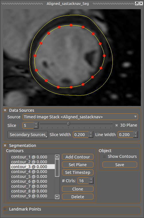
This is a specialization of the 2D view for defining segmentation contours, specifically for the left ventricle. It displays image and mesh information in the same way as the 2D view with the same mouse controls, but includes facilities for drawing and controlling circular contour segments which are used for creating mask images and meshes by plugins.
Contours are drawn to identify boundaries and define geometry for various tasks. Different plugins will use these contours to perform specific tasks which will be actuated through their UI controls without the need for use choice. For example, the short axis alignment process can use contours to automatically create a mask image needed for the alignment operations.
Since a contour must exist on one plane, that is its control points must all be coplanar, it will almost always be necessary to select an Image Stack representation object as the Source image. This ensures coplanar and parallel contours which are also evenly spaced apart.
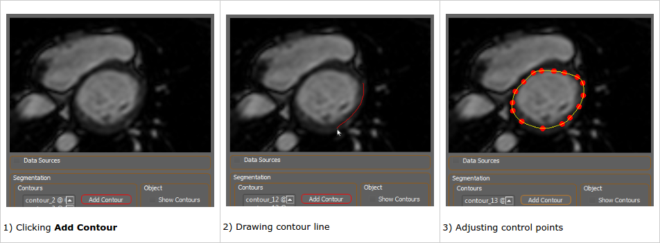
The user creates contours by clicking Add Contour, then left-click dragging the mouse to create a path where the contour should be defined. When the mouse button is released control points along the defined line are chosen for the new contour. The points can then be adjusted manually to best fit the subject. Existing contours can be clicked to make them active and allow their control points to be adjusted.
The sequence of images below illustrates this process:

The UI elements of the Contours box are as follows:
- Contours List: This list existing contours by their name and timestep. Clicking on one will make it the currently active contour whose control points can be moved.
- Add Contour: Click this to add a new contour on the currently-viewed plane at the current timestep. The button will remain red, meaning a contour can be drawn, until that operation is completed or the button is pressed again. While the button is red the image plane cannot be moved.
- Set Plane: This moves the currently selected contour to the currently viewed plane and ensures its control points are all on that plane.
- Set Timestep: This sets the timestep of the currently selected contour to be the current timestep. Each contour is associated with the time it was created for, thus one image series might have multiple contour definitions for the same geometry but at differing times.
- # Ctrls: This sets the number of control points for all the contours, which must always have the same number. Changing this value will cause existing contours to have their control points replaced by those re-interpolated at uniform intervals along the contour line, this will almost certainly affect shape so this should be treated cautiously. The default value of 16 was found to be sufficient for most tasks.
- Clone (icon with 2 boxes): Makes a copy of the currently selected contour and projects it to the current plane.
- Del (trashcan icon): Deletes the currently selected contour.
The UI elements of the Object box are as follows:
- Show Contours: Check this box to show the contour lines in the 3D view.
- Save: Saves the current contour information to the segmentation object's file.
The Landmark Points box is for choosing cardiac left ventricle landmarks needed for meshing. Once an image you wish to place a landmark on is set to be the source, you can place a landmark on the current plane by pressing Set Plane and then dragging the point around to place it where you want.
- RV Anterior Attachment should mark where the right ventricle meets the left on the anterior side, this is used to determine orientation around the left ventricle and the plane from which AHA regions are defined. The generated meshes will have elements assigned to AHA regions on the plane where this point is placed and below, anything above is placed in an ignored region.
- 2 Chamber Long Axis Apex should mark the very bottom of the apex of the left ventricle as seen in the 2 chamber image.
- 3 Chamber Long Axis Apex and 4 Chamber Long Axis Apex are for the apex as seen in the 3 and 4 chamber views respectively. If no long axes images are present then place one of the three apex points on the short axis at the best guess location of the apex.
A Segmentation Object can be created through the Create menu in Eidolon's main window. This will create the new object in Eidolon and add it to a project if one is loaded. To segment the left ventricle in a way suitable for creating meshes with correct AHA regions, follow these steps:
- Load the image you want to segment, if this is short axis load the long axis images as well if you have them.
- Create the segmentation object through the Create menu.
- Set the image you want to segment as the Source Image.
- Right-click on the segmentation object and select Show Segmentation View or click on the button with that label in the object's property dialog.
- Scroll through the image slices in the view until reaching the first frame which clearly shows a ring of LV myocardium and blood pool.
- Draw contours around the inner and outer surfaces of the myocardium on this slice and every slice below it so long as an identifiable ring of tissue and blood pool can be seen.
- The last frame where tissue is visible at all will be the apex or near to it, there will be no pool visible here and so no contours should be drawn here.
- Click Save at regular intervals to avoid losing your work.
- Place the RV Anterior Attachment landmark in the correct position using an image near the top of the left ventricle showing the right ventricle attachment clearly.
- If you have 2/3/4 long axis chamber views, load these, set one to be the source image, place the landmark point at the correct position, and repeat for the others. If you don't have long axis images, you will have to guess where the apex should be in the short axis image and set once of the points there. The generated mesh will take an average of the non-zero points as the position for the apex, so you may want to place a second point below the first so that the average is between slices.
- In the segmentation object's dialog you can choose to create meshes or mask images. Selecting Hemisphere Mesh in the Generate Mesh section then clicking Generate will create an LV mesh with assigned AHA regions.
- Adjusting the image spectrum will help in segmenting by making boundaries more visible, especially with CT. With the segmentation dialog open click on the image series that it currently is viewing and adjust its spectrum as needed.
- Turning texture filtering off in the image's properties dialog may help as well.
- Remember to save often. There's no undo/redo feature yet so if you, for example, delete a contour by accident, close the segmentation dialog and re-open it to reload what was saved to the scene object.
An LV segmentation can be used to align the short axis through the Short Axis Align dialog. The objective is to segment the first frame of the time-registered image (if a template image is being used) or first frame of the short axis itself (if a template is not used). This segmentation is then used to generate a mask image which the alignment procedure requires. All segmentations should be done at diastole which should be the first image in short axis series.
The process to do this is as follows:
- In the Short Axis Align dialog, select a template image or leave as None, and select a short axis image.
- Generate the time-registered image series if a template is being used
- Clicking Create Segmentation Object will create a new object in the project associated with either the time-registered image or the short axis image.
- Right-click on this object and select Show Segmentation View or click on the button with that label in the object's property dialog.
- A Timed Image Stack of the associated image series will be created if one doesn't already exist, and a 2D view like the one pictured above will appear.
- Scroll through the image slices in the view until reaching the first frame which clearly shows a ring of LV myocardium and blood pool.
- Draw contours around the inner and outer surfaces of the myocardium on this slice and every slice below it so long as an identifiable ring of tissue and blood pool can be seen.
- The last frame where tissue is visible at all will be the apex or near to it, there will be no pool visible here and so no contours should be drawn here.
- Click Save at regular intervals to avoid losing your work.
- Place the RV Anterior Attachment landmark in the correct position using an image near the top of the left ventricle showing the right ventricle attachment clearly.
- If you have 2/3/4 chamber views, load these, set one to be the source image, place the landmark point at the correct position, and repeat for the others.
- Once the segmentation is done, click Save again then select the segmentation object in the Segmentation field of the Short Axis Align dialog, then click Align Image Stack.
The segmentations are stored in a text file which conforms to the .ini file format for name/value pairs.
Contours are represented as lists of points in 3D space which are used as the control points for a piecewise Catmull-Rom line.
There are a few required name/value pairs but others can be included to define other properties, however contours must always be named contour_## and be uniquely named.
Required values:
- name: name of the segmentation
- srcimage: name of the image object the segmentation was defined for
- type: what type of structured is segmented, eg. "LV"
- title: window title
- contour_##: a defined contour line. This is stored as a pair containing the time the contour is defined at and a list of float triples, each triple representing a point in 3D space.
Example file:
[DEFAULT]
ch2Apex = (0.0, 0.0, 0.0)
ch3Apex = (0.0, 0.0, 0.0)
ch4Apex = (0.0, 0.0, 0.0)
contour_01 = (0, [(74.84780713919383, -43.344159494829725, 43.0), (108.9387230937763, -74.39123693477623, 43.0), (75.76095960534914, -109.09091513568528, 43.0), (42.27881124792605, -75.00000256714058, 43.0)])
contour_02 = (0, [(47.45332441205503, -75.30438683473452, 43.0), (75.1521877265248, -46.996756772404055, 43.0), (104.0685884124311, -75.00000256714058, 43.0), (76.0653401926801, -103.9163976812707, 43.0)])
name = 'Segment'
rvAttach = (0.0, 0.0, 0.0)
srcimage = 'Sphere'
title = 'Segment'
type = 'LV'