Bogie Assembly
ExoMy is comprised of three bogies. One on each side and one on the rear. This locomotion design is also used on the ExoMars rover and is called triple bogie.
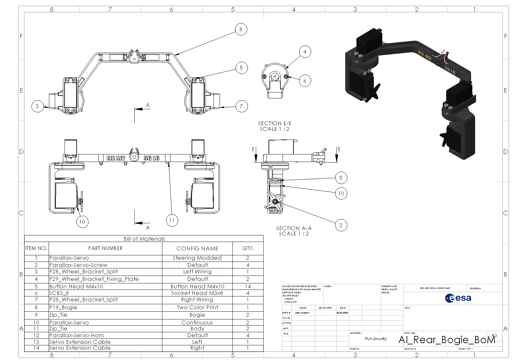
All three bogies are designed in the same way. In fact, they are one and the same file in SolidWorks with varying dimensions for the side and rear bogie. Thus, only the assembly of the rear bogie will be showed. The side bogies should be assembled the same way.
Electrial Tape (any color works, but maybe fitting the bogie)
Before installing the steering motors, check that you modified them as explained in the electronics section here. Make sure you install the standard, 180 degree rotation, and not the continuous rotation servos into the bogie!
A means of restraining the bogie (vice or a second pair of hands) can help a lot in this assembly phase.
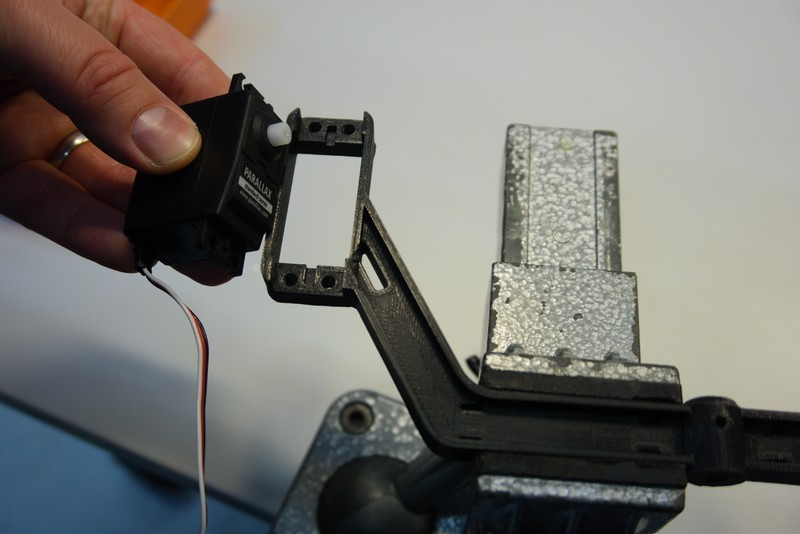
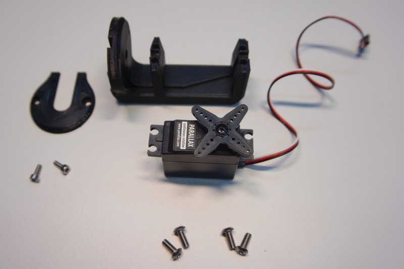
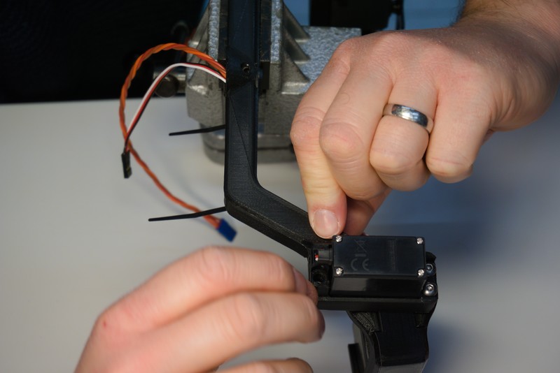
To begin, remove the cross-shaped flange from the servo and store it together with the screw for later. The servo is placed into the bogie with the axis furthest away from the bogie, as shown below.
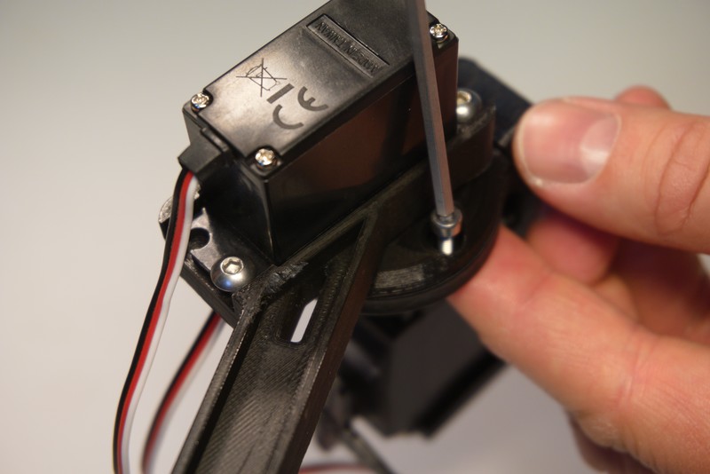
Install only three of the M4x10 button screws on each side as depicted bellow. The final screw hole, top left and top right respectively, will be used to mount the cable cover at a later stage.

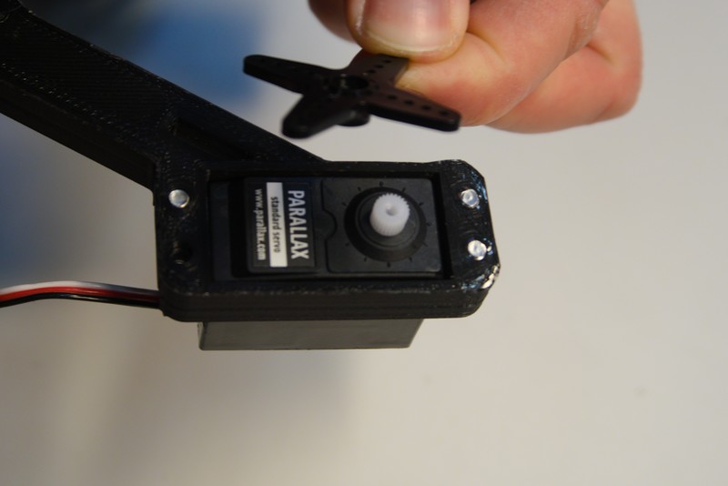
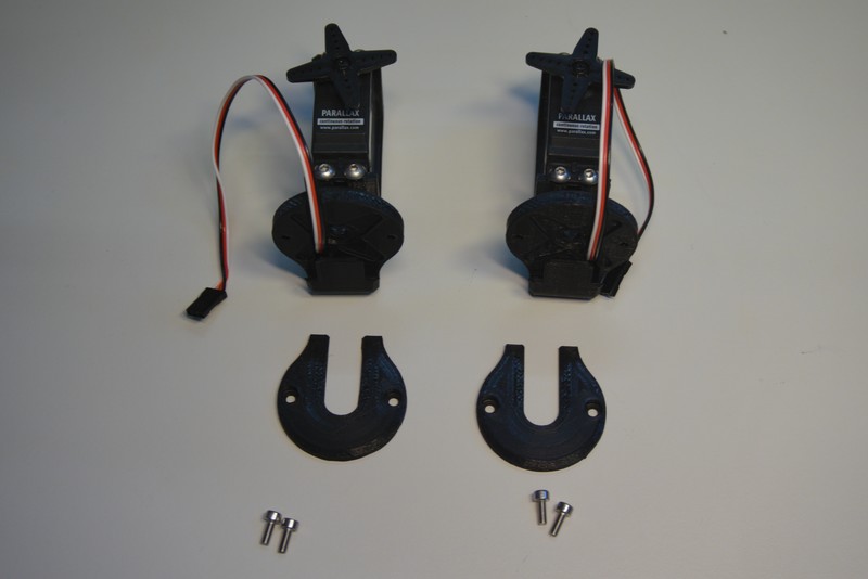
Now, reinstall the flange to the servo motor. It is important to install it at the correct angle. The wheel brackets should be able to rotate with range of motion of +- 90° as depicted in the picture bellow.

To achieve this, place the flange on the shaft and rotate it left until the endstop.

Now the middle, or zero, position shall be determined. In our case, the steering motors have a rotation range of 180°. So the flange is rotated right from the endstop by 90° to reach the middle position. If your servo has a different range of motion, you will need to move the servo by range_of_motion÷2.

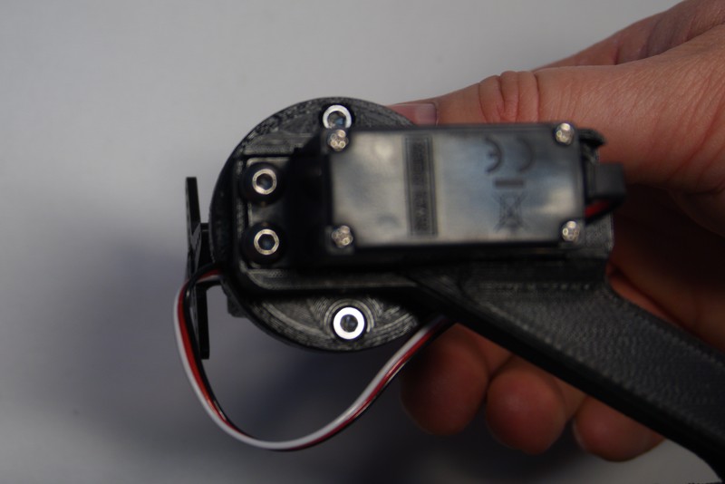
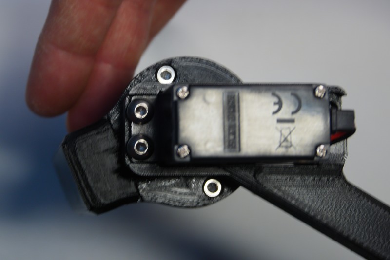
With the servo in the middle position, remove the flange and place it in a 45° rotated orientation as shown bellow.

Mount the flange screw to finish the motor installation.

During use of Exomy the cables may rub on various parts and might get slowly damaged. It is therefore recommended to apply some kind of cable protection. It's kind of a good moment now, or at least keep it in mind in later steps, when routing the cables from the wheel assembly to the bogie and then through the housing.
The main areas of wear are:
- inside the "P28_Wheel_Bracket" (specifically on the top inside turn)
- after leaving the "P28_Wheel_Bracket" until passing the first zip tie inside the "P19_Bogie"
- from the bogie into the housing passing through the "P03_Bogie_Bearing"
It has proven useful to use electrical tape and wrap the concerned areas longitunal carefully. Use a strip of tape and lay it parallel to the wire and fold it neatly around it.
The following picture shows an example of the result:

For more pictures check out the referenced issue.
If you notice during driving around later, that the cables tend to touch the wheels, you can use rubber bands or maybe even springs to tie them upwards. For the center wheel assembly a small modification is recommended in this case. The cable of the driving motors should not exit the regular way, as described below, but sideways on the top of the "P28_Wheel_Bracket". Therefore you should remove on each side of "P29_Wheel_Bracket_Fixing_Plate_Default" one end that slides under the "P28_Wheel_Bracket" allowing for enough space for the cables. Afterwards you will be able to route the cable out sideways and pull it up with the rubber band.
The following modification needs to be applied to the two center "P29_Wheel_Bracket_Fixing_Plate_Default":

The result after routing (see later steps) would look like this:

Next, the driving motors shall be installed in the wheel brackets. You can do this directly for all six wheel brackets.
Again, make sure you have the continuous rotation servo.
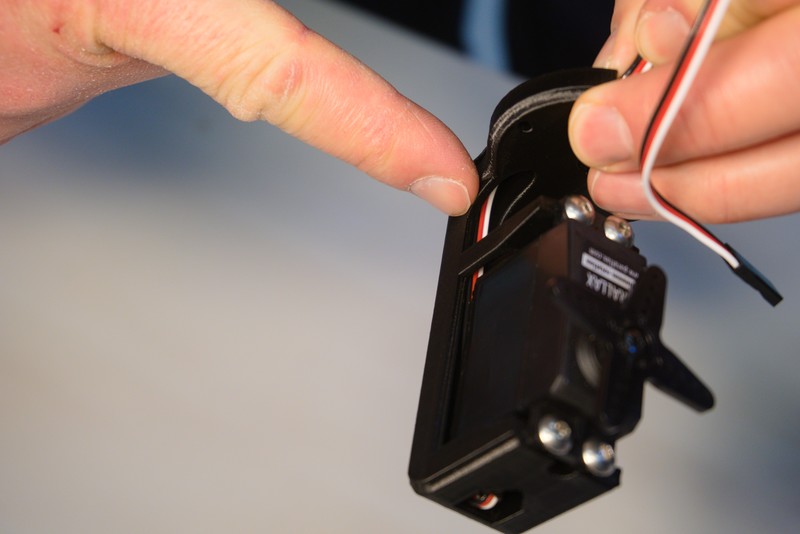
Begin with routing the cable through the wheel bracket.

The cable should be sitting neatly in the cable channel behind the motor. Make sure it does not stick out of the wheel bracket at the bottom.

With the cable snuggly routed, it is time to fasten the motor to the bracket. Use again the M4x10 button head screws.

Do not install the wheels yet. First, the driving motors have to be calibrated, which will be done in the final integration.

Make sure the servos are positioned in the middle position as described above. Pay attention that you use the correct wheel bracket. Two versions exist that have the cable channels routed either on the left or right side. The rear and side bogie have the two varinats swapped so make sure to check in the technical drawings which version to use where. Otherwise you will have too much slack in your cable.
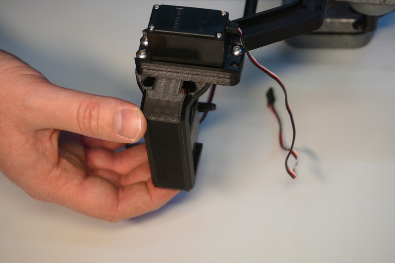
Now place the wheel bracket under the servo flange. The lip which must go above the flange as shown below.
Move the cable all the way to the back, so it is flush against the wheel bracket.
Slide the wheel bracket mounting plate in. This bracket will also clamp and restrain the cable of the driving motor.


Rotate the servo so you have access to the two mounting holes. Use the M3x8 socket head screws to restrain the wheelbracket to the steering motor.

To finish the bogie assembly, the cables have to be routed nicely along the bogie. Four zip ties and two PWM extension cables are needed for this step.

Begin by routing the driving motor cable up to the cable channel.

Next, connect the PWM extension cable to the driving motor cable. The connector can only be plugged easily in one way, so make sure you don't force it in the wrong way around.
Move the steering motor to both end stops and ensure that enough play is available for the steering motor to turn it's full range of motion.
Then lay both the steering and driving cables into the cable channel. The extension connector was positioned between the two zip tie cut outs in our case. This might be different for you, if you have different motors with different cable lengths.

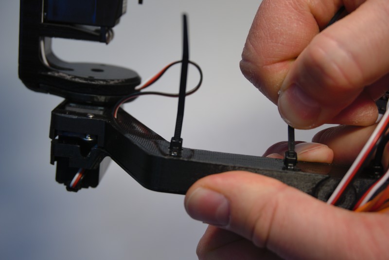
Install the two zip ties but do not fully tighten them yet!

Place the bogie cable cover on top of the bogie to check the fit of the cables. The cover should sit flush on the bogie without clamping down on any cables.
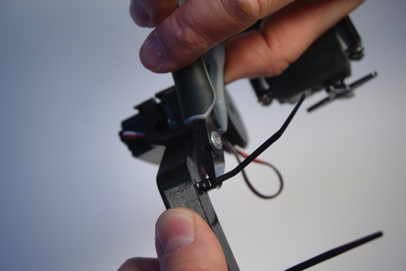
Once the cable cover is fitting neatly, double check the range of motion of the steering motors and adjust the cables accordingly.
Then tighten and cut the zip ties.

The cable cover will only be installed at final integration so put aside and carry on with the assembly of the other two bogies.
Once the side bogies are built, continue by building the head assembly.