Electronics
In this chapter you will be learning how to solder and adjust the wire harness, solder the PWM board, reroute the cable of the steering servos and finally test the electronics.
The instructions were made at home during the COVID-19 quarantine, thus some tools and parts look slightly different, than in the other parts of the instructions.
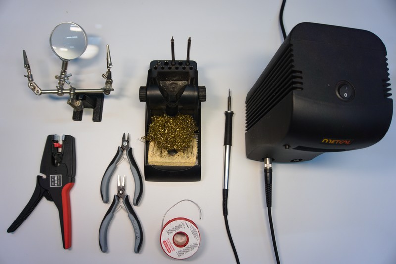
Necessary Tools
- Soldering iron and lead
- Pliers
- Multimeter
Optional Tools
- Helping hands
- Insulation stripping tool

It is always a good idea to rigidly mount the helping hand to the table.

The wire harness can be soldered using different kinds of wires. In this instruction, solid core wire was used. The wire harness in other parts of the instructions contains stranded wire however.
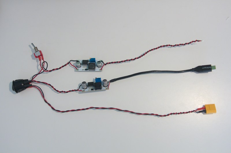
Begin by making sure you have the required parts as depicted bellow.
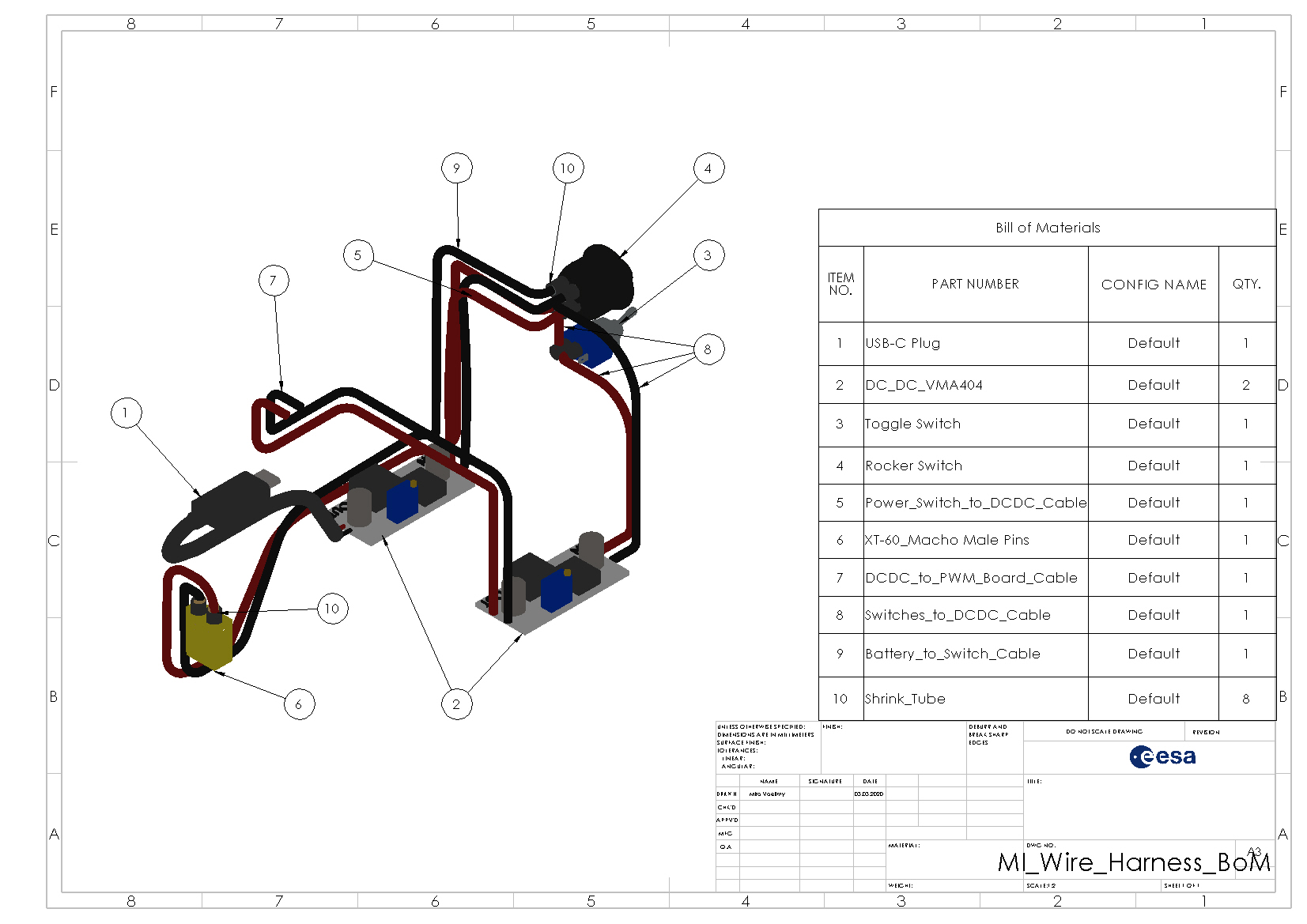


Throughout the tutorial it is always recommended to double check your progress with the schematic depicted above.
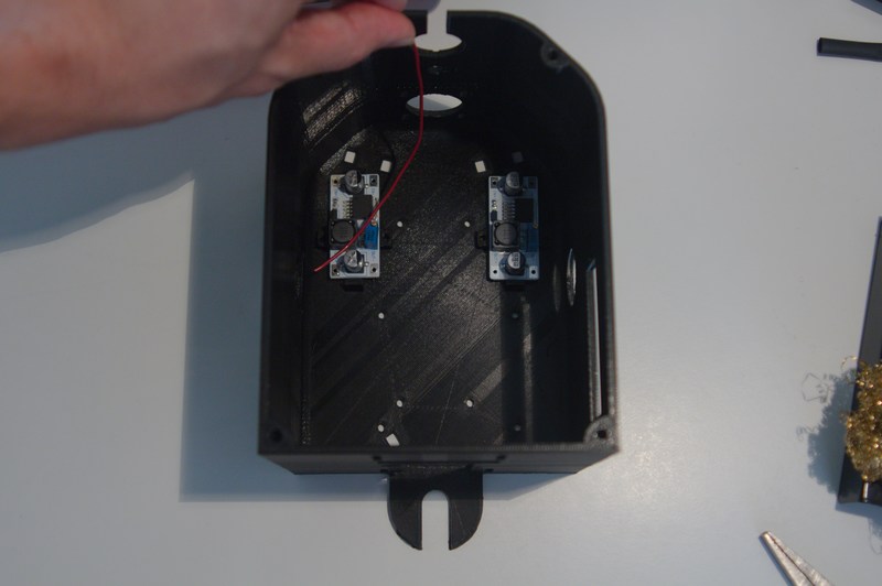
First, all cables connected to switch 1 are measured and cut within the body. Be generous and measure them longer then necessary.
If you are using solid core wires, it is recommended to twist them for a tidier look and to reduce electromagnetic interferences. Cut your cables a good portion longer in that case as the twisting will shorten the total cable lenght.
The cables to be cut are:
- Switch 1 -> Battery - GND & V+
- Switch 1 -> DC/DC 2 (Raspberry Pi) - GND & V+
- Switch 1 -> Switch 2 (motor switch) - V+
- Switch 1 -> DC/DC 1 (motors) - GND
Remove the insulation from all cables.

Twist the GND cables going from switch 1 to DC/DC 1 & 2 and the V+ cables going from switch 1 to DC/DC 1 and switch 2.


Then solder them to the middle pin of switch 1. Solder the battery cable to the outer pin of the switch.

Use a multimeter (in beeper mode) to double check that the GND wires and the V+ wires are connected correctly.
The switch should look like this after all cables are soldered correctly.

Cut the heat shrink tubing to size and place it over the switch contacts.

Use a heat gun or a lighter to shrink the tubing.

Measure and cut the cables from DC/DC 1 to the PWM board. Again, cut the cables a tad to long. They can always be shortened later.
The black cable is connected to 'OUT-' and the red cable to 'OUT+'.

Begin again by laying out the cable and cutting it to length.

If you are using a USB data cable you will have to find the GND and V+ strands. If you are using a USB power cable, it should only contain a black 'GND' and a red 'V+' wire.
In our case, there were two unshielded bundles of wires as GND and a red wire with V+.
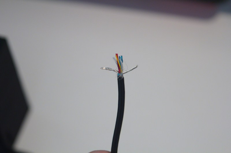
Twist the GND wires together and cut away the data cables (orange, green).

Before soldering the cable to DC/DC 2 make sure you place a piece of heat shrinking tube over the cable.

Solder the GND cables to 'OUT-' and the red cable to 'OUT'.

Shrink the previously place heat shrinking tube as depicted bellow.

In case your switch has three connectors (ON-ON type switch), remove one of the side connectors to change it into a ON-OFF type switch. This will reduce the chance of shorts.


Next, measure a cable from switch 2 to DC/DC 1 and solder it to the middle terminal.

Place a piece of heat shrink tube over the shortest red cable coming from switch 1.

And solder said cable to switch 1.

Place a second piece of heat shrink tube and shrink it.

Make a test fit in the body. It should look similar to the picture bellow.

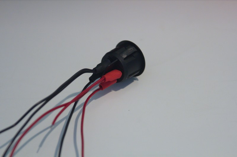
Depending on the battery used, a different battery connector has to be used.
Before soldering, place two pieces of heat shrinking tube over the cable and then solder them to the connector.
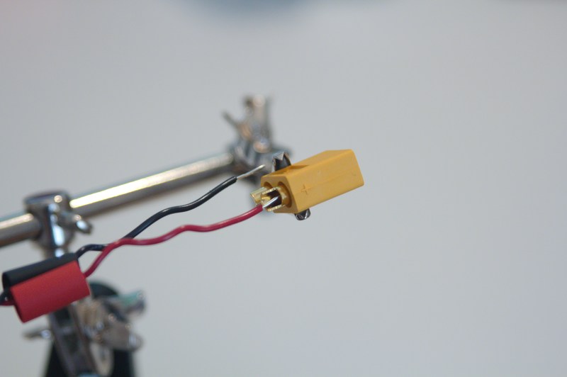
Shrink the heat sink tubing in the same fashion as before.
You should now have both DC/DCs with cables soldered on their OUT pads and a wire
Make sure you connect the DC/DC 2 (with USB cable) directly to switch 1. DC/DC 2 (wires without connector) has to be soldered to the output of switch 2 and GND coming from switch 1.
Place them in a helping hand solder the parts as shown bellow.

If your harness looks as follows proceed to set the DC/DC converter voltage as described in the next chapter.
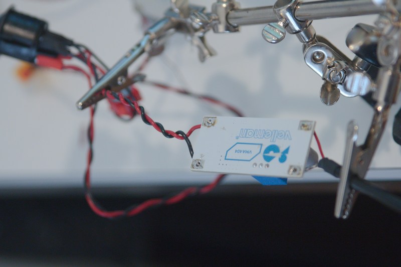
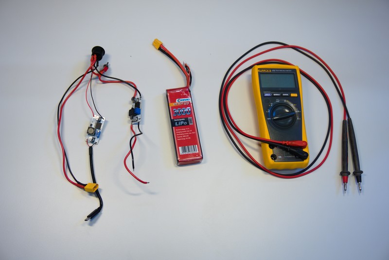
The output voltage of the DC/DC converters can be adjusted using the blue potentiometer. It is important to carefully set the correct voltage in order not to damage the Raspberry Pi or the motors. You will need the wire harness, that you finished in the previous step, the LIPO, a thin flathead screwdriver and a multimeter (preferably with some clamps).
Turn off the power and motor switch and connect the LIPO to the wire harness.
The DC/DC converter with the USB cable will power the Raspberry Pi and should be set to 5V.
Activate the main switch and measure the voltage between the two output terminals on the Raspi DC/DC converter. It helps to use a friend or some multimeter clamps to hold a steady connection to the terminals while you adjust the potentiometer.

Check in the motor datasheet, what the maximum rated voltage of the motors is. Our motors are rated for 6.0V, so the motor's DC/DC is set to 6.0V in the same way as the Raspi DC/DC converter.

Sometimes the PWM boards are shipped with the connectors not soldered yet. If that is the case for you, you need to solder the connectors in place. Here you can find a good instructional video on how it is done. The video uses long headers, but our guide uses short ones.
For this test you will need:
- Raspberry Pi with the software installed as described here
- Charged LiPo
- PWM board
- Servo
- HDMI cable
- Display
- Mouse and keyboard
The test should verify that the electronics, PWM board and servo motors work as expected. You will move a single motor using a command line script. It is recommended that you do this with a continuous and a standard servo motor.
- Connect all electronics as shown in the schematics above.
- Disconnect the Lipo and set all switches to OFF
-
Connect the Lipo
- Nothing should happen
-
Set the switch 1 to ON
- The Raspberry Pi should boot, which is visible by the blinking LED.
-
Measure on the input pins of the PWM board
- Voltage should be 0V
-
Set switch 2 to ON
- Measurement on the input pins should show your set voltage now (6.0V in our case).
-
Connect motors
- Turn switch 1 OFF.
- Plug a continous and a standard servo motor into the PWM board. Make note of the pin number as you will need it in the next step.
- Turn switch 1 ON.
-
Test the motors
- On the Raspberry Pi start the motor_config_docker as described here
- Make sure you are in folder
/root/exomy_ws/src/exomy/scriptsand otherwise runcd /root/exomy_ws/src/exomy/scripts - Run the motor test script with
python motor_test.py PIN_NUMBERwhere you replacePIN_NUMBERwith the one where you connected your motor to. - Choose
2. Incremental positioning. - You can now play around with the motor and verify that it works as intended.
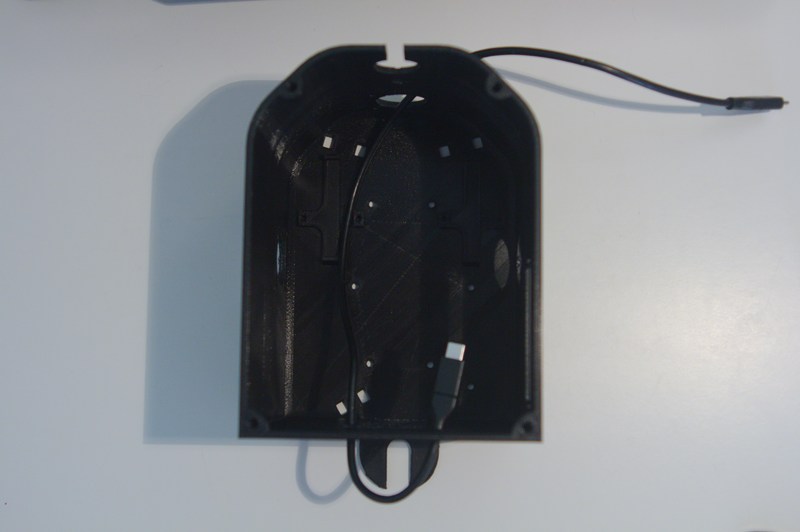
For a cleaner aesthetic and 100 style points, it is recommended to route the cable of the steering motors inside of the casing instead of externally.
This step isn't required, but neither is bathing. Think about it.
Begin by fixing the motor in a vise and removing the screws.

Remove the cap to reveal the PCB.

Next, carefully cut a slit into the black plastic seal using pliers. It will be move to the other side of the casing after rerouting the cable.

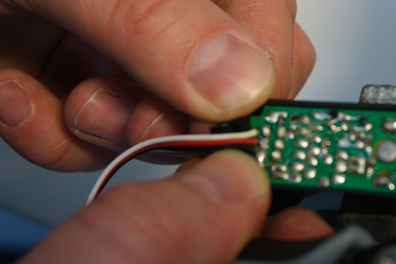
The cable will afterwards run across the PCB. The Pins from the components would spike it and create a short.
It is thus very important to cut the pins as short as possible. Use your pliers to carefully cut the pin in the center, where the cable will be laying.
Do not cut multiple pins at the time as you could rip out traces from the circuit board by doing so.
The cut off pins will fly away! Wear safety glasses!

Route the cable across the freshly cut path and reattach the previously cut cable seal.

Now, reinstall the cap. Make sure reorient it so the cutout in the cap is on the side of the seal! Otherwise, your cable will not fit.
