-
Notifications
You must be signed in to change notification settings - Fork 11
Device Tree overlay
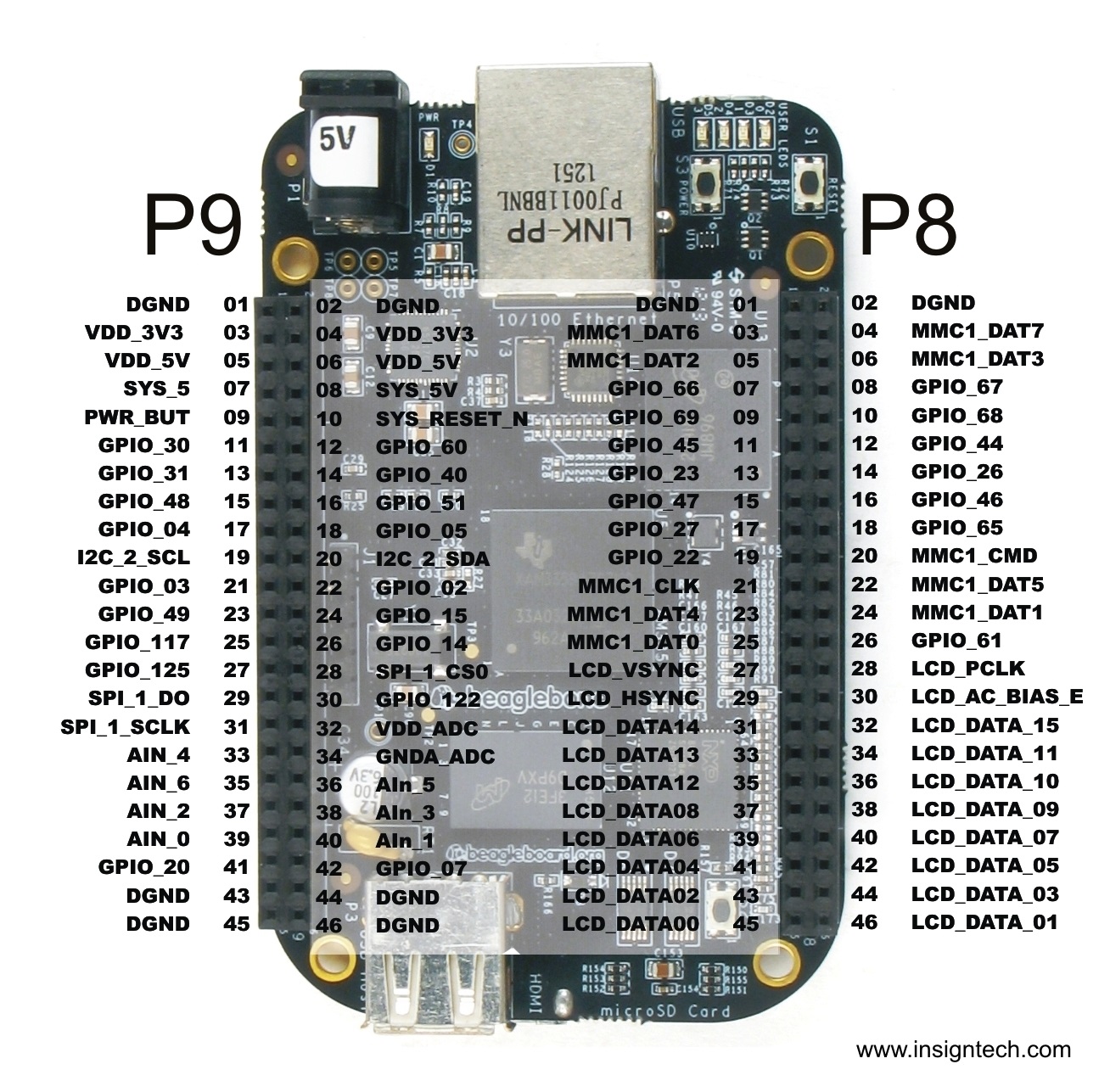
When creating an device tree overlay, one must consider which pins on the P9 and P8 header are not being used by the beaglebone board. Below is a Figure that details the initial state of the pins at boot up.
 Above is a spreed sheet of the available pinmux assignments for the p8 header. The pins that are marked in red are used by the beaglebone board. Pins 34 through 46 are tied to the boot configuration pins and the HDMI. These pins can be used after the ROM has been initialized. Any devices that is hooked up to these pins will need to be in the high impedance state on boot up. Pins 3 through 6 and 20 through 25 are tied to the emmc loader. These pin can not be used unless booting from a sd card. The bone will not boot if emmc overlay is disabled. The rest of the pins should be ok to use.
 Above is a spreed sheet of the available pinmux assignments for the p9 header. As before the pins marked in red are being used by the bone. Pins 19 and 20 are being used for i2c cape communication. Pins 28 through 31 are being used for spi communication. All other pins are fine to use for any application.
For most of the communication protocols, there is a overlay already created and all it needs to be done is loaded the overlay into SLOTS. All available overlays are located in the following directory: /lib/firmare.
Due to the number of GPIO pins, it is not practical to have an overlay for each GPIO pin. So this leads us to create a custom overly for the GPIO pins that is need to be used.
Here is a link to Derek Molloy Device Tree tutorial.
http://derekmolloy.ie/gpios-on-the-beaglebone-black-using-device-tree-overlays/
Here is a link to Derek Molloy Device Tree github page. https://github.com/derekmolloy/boneDeviceTree
