-
Notifications
You must be signed in to change notification settings - Fork 5
Detection arm assembly
Benchtop-partslist-latest.xlsx
The F (focus) stage is the first step of Benchtop building.
🔧 The angles of mechanical components should be kept at right angles to simplify optical alignment later. Use the try square to keep edges of components at right angles, before bolting them together.
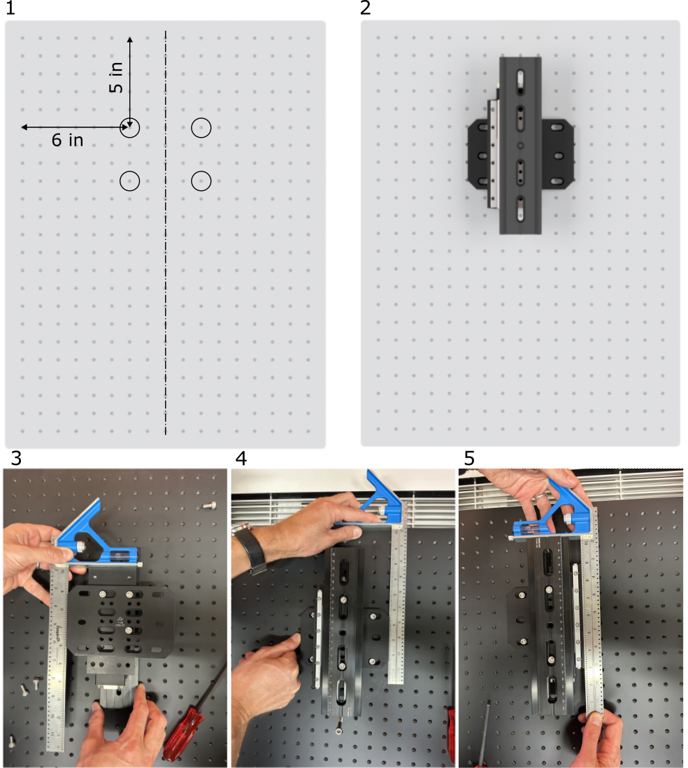
- Locate the top left M6 mounting hole on the breadboard as shown.
- 3D model of the mounted F-stage
- Adjust the angle between F-stage and its mounting plate with the try square, then tighten the bolts.
- Align the F-stage mounting plate with the base breadboard edge, then tighten the bolts.
- Align the XT66SD-250 rail with the stage edge, then tighten the bolts.
❗ The center of the rail XT66 must be along the breadboard center line.
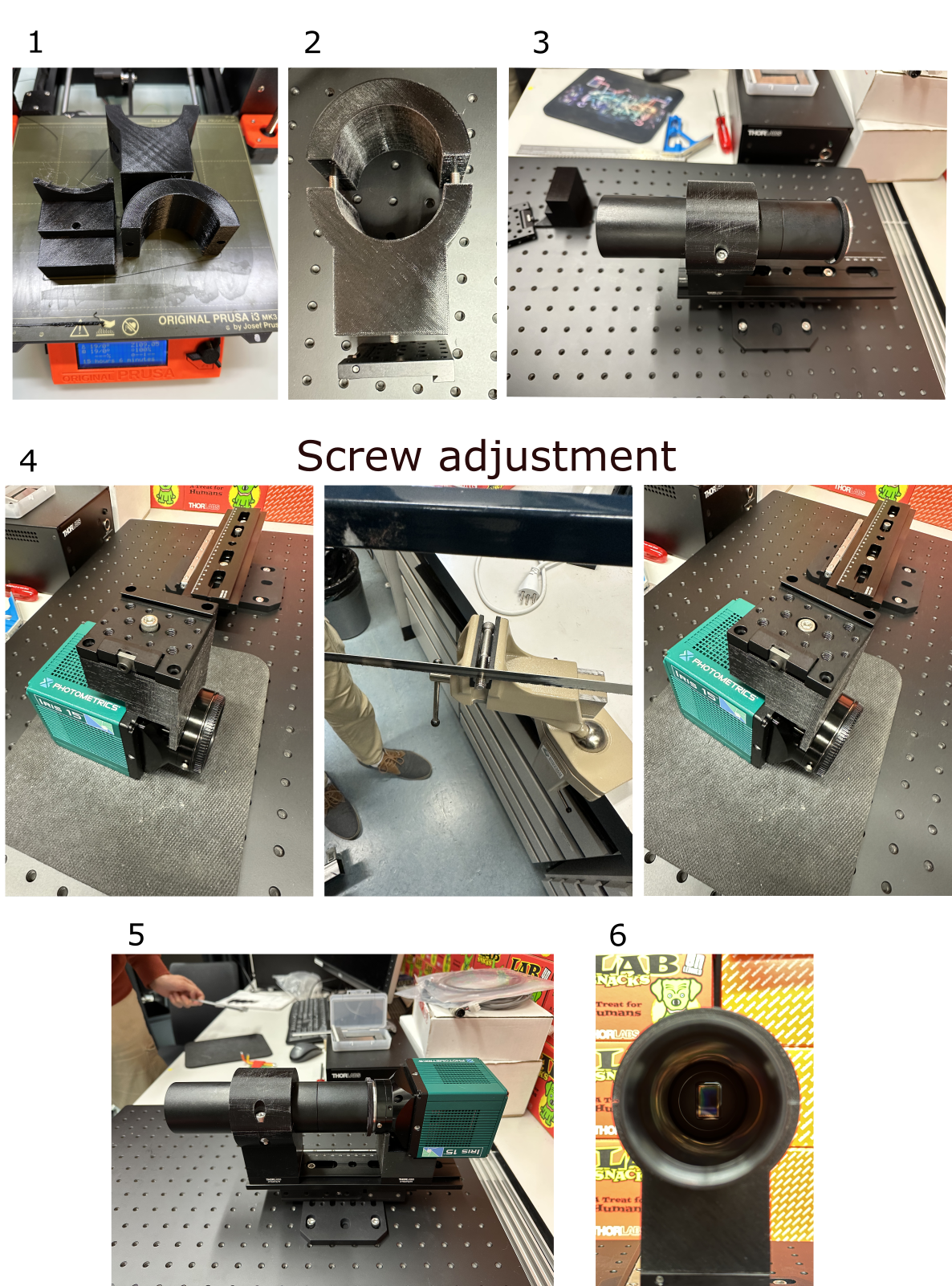
For camera mounting, 3 parts must be printed (ThorlabsSM2L30-XT66P2M-BASE, ThorlabsSM2L30-XT66P2M-TOP, Iris15-XT66P2M). See /custom-parts/detection-objective-mounts for the STL models.
🔧 We use Prusa 3D printer with PETG filament, since dimensional accuracy is not very critical for these parts.
- Print the parts, remove any strings/hair with a coarse sand paper if needed (PETG tends to print with a lot of stringing)
- Bolt the ThorlabsSM2L30-XT66P2M-BASE and ThorlabsSM2L30-XT66P2M-TOP together with M6 screws/nuts, and attach the base to the XT66P2/M rail carriage.
- Screw the two SM2 tubes together, attach the F-mount, and place it into the 3D printed mount on the XT66P2/M rail carriage.
- The Iris 15 camera has imperial mounting thread 1/4-20, which is rather shallow. Cut 5 mm off the 50-mm long 1/4-20 mm bolt (the longest in Thorlabs 1/4-20 kit), using wise and a hand saw (for metal). Use the shortened bolt to mount the Iris 15 camera on the Iris15-XT66P2M pedestal and the XT66P2/M rail carriage.
- Attach the camera to the F-mount.
- The camera should be oriented with the longer sensor size vertically, and the data port on the top. Sensor orientation is important for the rolling shutter mode readout running horizontally.
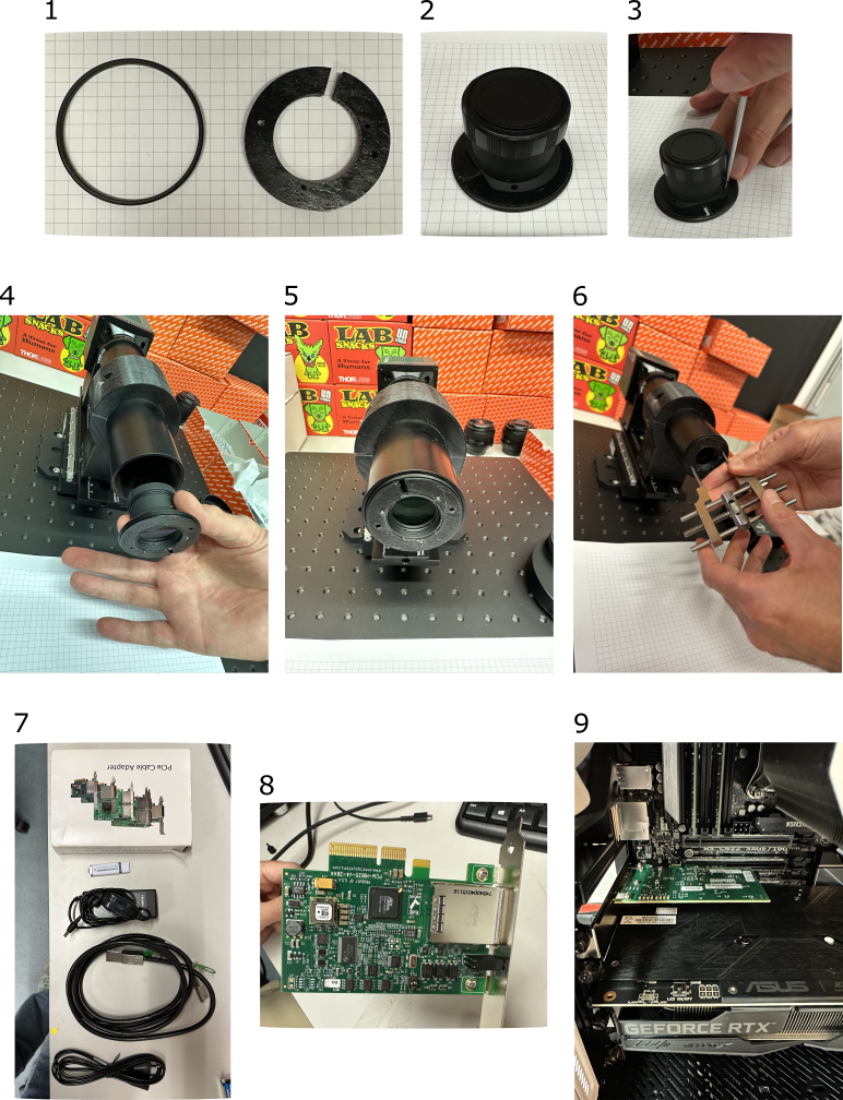
- 3D print the adapter (Adapter-MitutoyoMT1-SM2-v2(flex).stl) for Mitutoyo MT1 tube lens. Take SM2 retaining ring, and insert the adapter into the ring (this requires some manual force).
- Insert Mitutoyo MT1 tube lens into the adapter
⚠️ Be careful when handling the tube lens, avoid contamination with finger prints.
- Fix MT1 in the adapter with 3x M2 screws.
- Insert the MT1 into SM2 tube.
- Start turning to catch the thread.
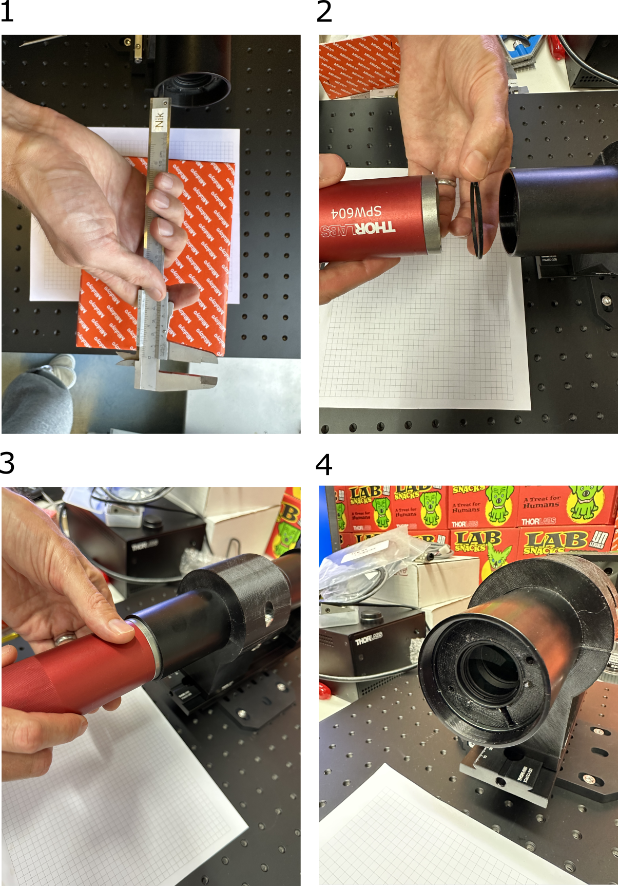
- Use Thorlabs Adjustable Spanner Wrench SPW801 to screw the tube lens in by about 10 mm.
- (8,9) Unpack the Iris 15 camera and insert the frame grabber card into free PCIe slot of acquisition PC.
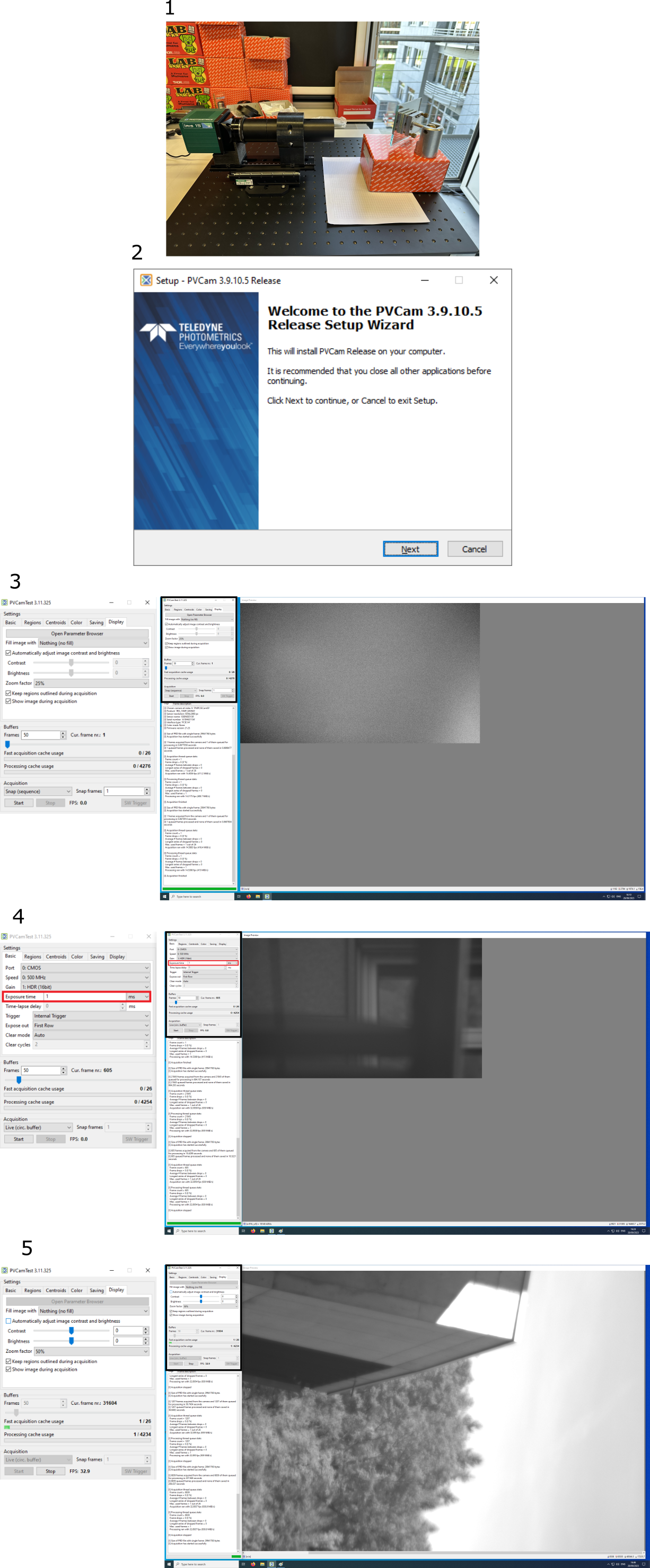
The tube MT-1 lens has a focal distance of 200 mm, which has to be set precisely relative to the camera sensor.
- Point the camera to a distant landscape (500 m or more should suffice), use a large folding mirror if necessary (eg to avoid obstructions).
- Insert the Photometrix USB key and install the PVCam Setup software.
- Connect the power and data cables to the camera and turn the camera ON. Reboot the PC.
- Start the PVCamTest software. It should recognize the connected camera. If not, reboot PC again.
- Start imaging in Live mode and adjust the exposure time if the image is too dim or too bright.
- Focus on distant, high-contrast landscape features, and adjust the software zoom factor if needed.
- 🔧 Use Thorlabs Adjustable Spanner Wrench SPW801 to adjust the tube lens distance until you reach the best possible focus. This may take about 10 min of slowly moving the lens in and out of focus.
- We measured the distance from SM2 tube edge to the 3D printed tube lens adapter to be 10.5 mm. This can be different if you use another tube lens or adapter.
- Insert the SM2 retaining ring.
- Fix the tube lens position with the retaining ring.
- Final position of the MT-1 tube lens.
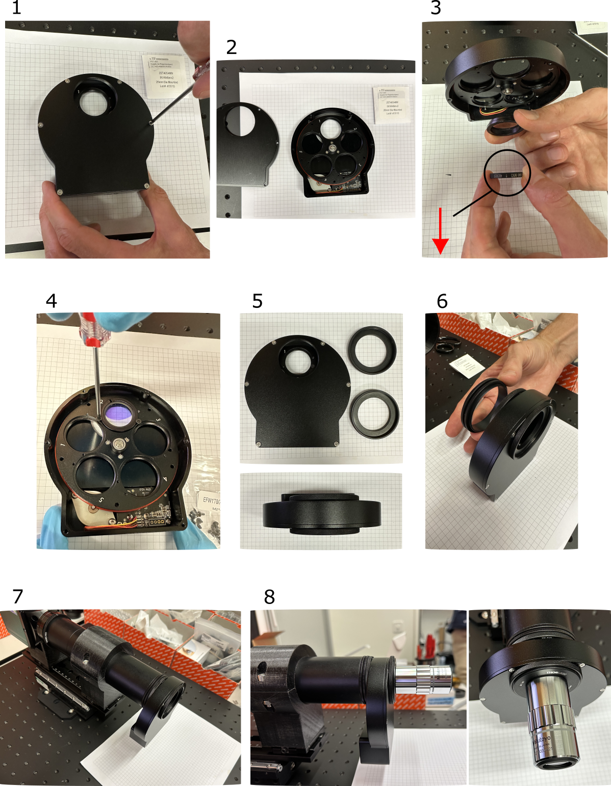
Here we use ZWO EFW Mini filter wheel and a 25-mm mounted quadband filter from Chroma.
If you are new to optical filters, please read this one-page manual from AHF: Handling of Optical Filters.
- Unscrew the filter wheel's top plate
- Remove the top plate, and prepare your filter (QuadLine Rejectionband ZET405/488/561/640 in 25 mm diameter, from Chroma)
- Carefully take the filter out of the package and insert in the 3D printed adapter ring (model file 25mmFilterAdapter.stl)
⚠️ I wear no gloves on the photo (my bad), but I put them shortly after, to avoid contaminating the filter.⚠️ Depending on filter manufacturer and model, the caret (arrow) must point either away or toward the detector. Check the filter documentation, e.g. Chroma emission (m) filters should be placed with the arrow pointing toward the specimen and away from the detector/eye. On the contrary, Semrock BrightLine, RazorEdge, EdgeBasic and H series as well as notch filters are mounted with arrow in the direction of light, towards the detector.
- Gently tighten two mounting screws (from the filter wheel box) to hold the adapter in place. Don't over-tighten to avoid filter damage!
- Screw on two adapter rings TMA4
- Attach the SM2T2 coupler.
- Attach the filter wheel to the SM2 tubes
- Attach the Mitutoyo objective with SM2A6 and SM1A27 thread adapters (works also only with SM2A6 adapter, as on the photo, because SM1 1.035"x40TPI and M26x36TPI threads are similar).
👏 Congratulations! The detection arm is now assembled.
The detection path can have two interchangeable configurations, described below.
Large-FOV plan apochromat infinity-corrected objectives with a suitable tube lens.
- magnification range: 2x - 20x
- NA range: 0.05 - 0.28
- lateral resolution: 2.5 - 1.5 microns
- filter wheel: 5-pos Zwo EFW mini
- filter wheel mounting: in the infinity space (between objective and tube lens)
- filter diameter: 25 mm
Industrial telecentric lenses with high field flatness.
- magnification range: 0.9 - 2x
- NA range: 0.04 - 0.1
- lateral resolution: 5.5 - 2.5 microns
- filter wheel: 5-pos 3D printed wheel controlled by a Dynamixel servo.
- filter wheel mounting: between the sample and the objective, on the optical table.
- filter diameter: 50 mm
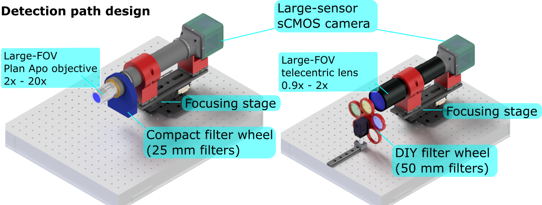
In both configurations the camera and objective are mounted on a focusing linear stage which adjusts the objective position to match the light-sheet illumination plane.
Red parts are 3D printed holders for the objective and the camera.
- Overview
- Room requirements
- Safety
- Parts list
-
Assembly
- Overview
- Detection arm
- Excitation arms
- Sample stages
- Electronics
- Lasers
- Immersion chambers (TODO)
- Front cover (with webcam)
- Enclosure (TODO)
- Usage
- Troubleshooting and typical errors (TODO)
- Maintenance(TODO)
- Technical notes
