-
Notifications
You must be signed in to change notification settings - Fork 5
Excitation arms assembly
Nikita Vladimirov edited this page Nov 6, 2024
·
21 revisions
Left and right arms are symmetrically identical, so only the components of left arm are shown below. Red color indicates custom-made or modified components. Unless specified, other part numbers are from Thorlabs catalogue.
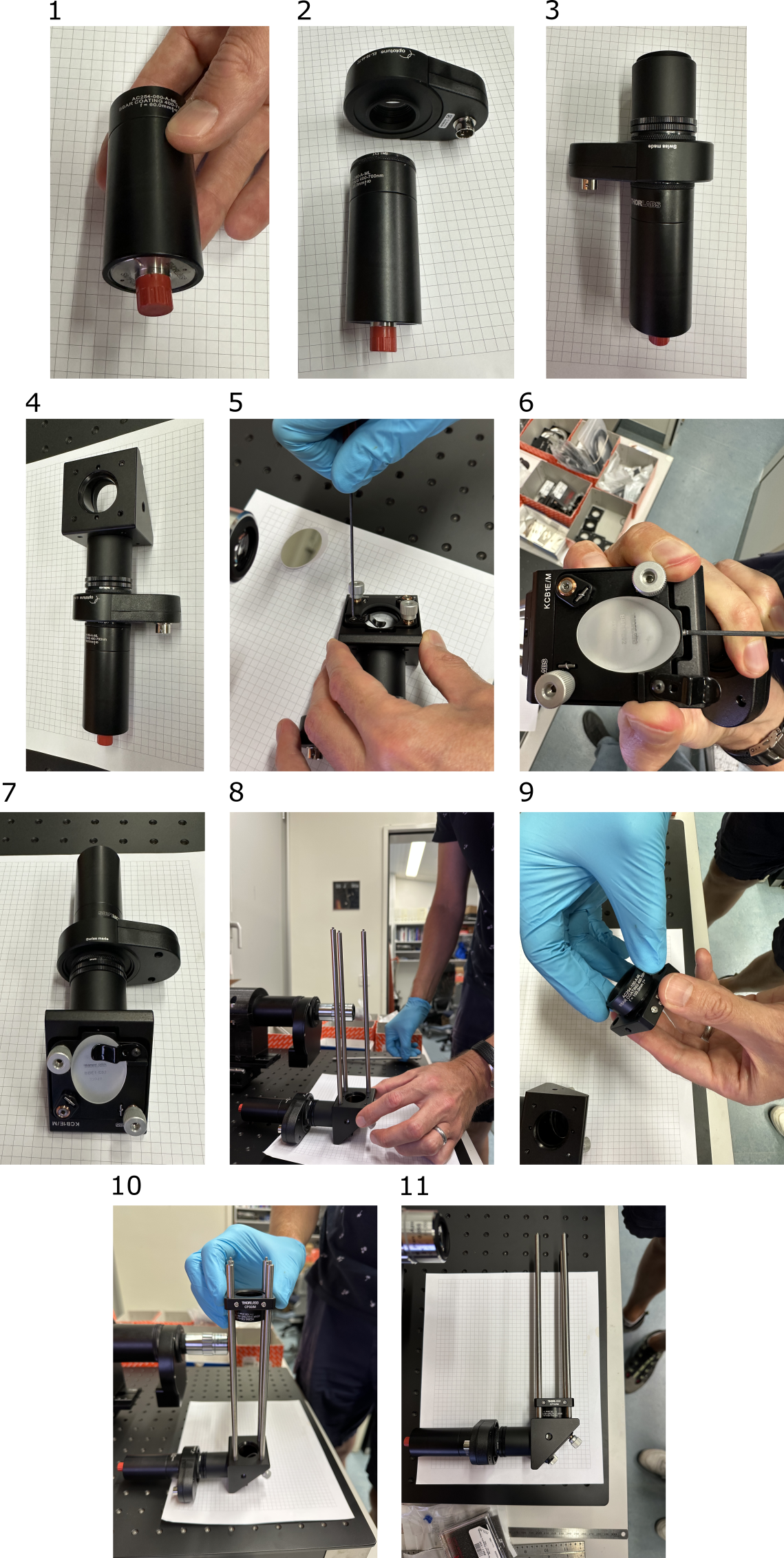
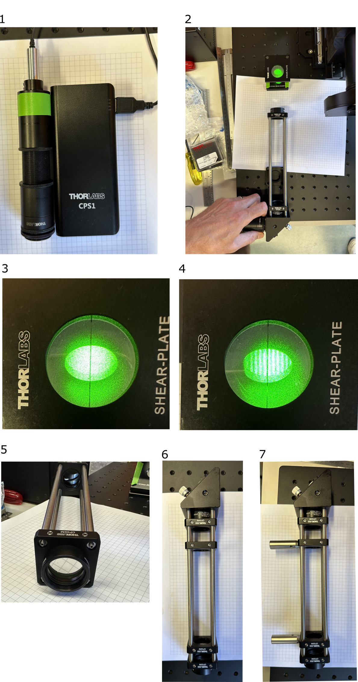
- Insert the fiber adapter plate SM1FCA into the stacked SM1 lens tubes (SM1L03+ SM1M20) on one side, and achromatic lens AC254-060-A-ML on the other. The fiber adapter plate SM1FCA should sit approx. 5 mm deep, measured from the edge of lens tube SM1L03. The exact position can be adjusted with shearing plate interferometer, see the image below. The fiber tip should be at the focal distance of the lens achromatic lens AC254-060-A-ML, so the output laser beam from this assembly should be collimated.

- Attach the SM1A10 thread adapter and the Optotune electro-tunable lens (ETL).
- Attach the thread adapters and SM1L10 SM1 1" tube.
- Attach the kinematic mirror mount
- Release the holding lever
- Unscrew the plastic-tip screw to make space for the elliptic mirror, so the mirror sits flat in the mount.
- Put the holding lever back, to fix the mirror in place
- Attach rods
- Mount the achromat in the cage plate
- Place the 100-mm achromat with the ♾️ ⬆️ facing the toward ETL (collimated beam side).
- Tighten the screws.

- If available, use a laser collimator and a shearing interferometer. See mesoSPIM V5 alignment tools wiki for details.
- Insert the second 100-mm achromat with the ♾️ ⬆️ facing away from ETL. Direct the beam into the shearing interferometer.
- Non-collimated beam, the distance between the two 100-mm achromats is incorrect.
- Move the second achromat closer or further away until the stripes align with the center line of the shearing interferometer. The beam is now collimated.
- Mark the distance where the second achromat is located. If laser collimator and interferometer are not available, you need to place the achromat in the position shown, with rod end screws sticking out 3 mm.
- Ah, and don't forget to put the two empty cage plates in between the lenses, they will be used for mounting the arm on the breadboard. Now you can finally fix the second relay lens in its place.
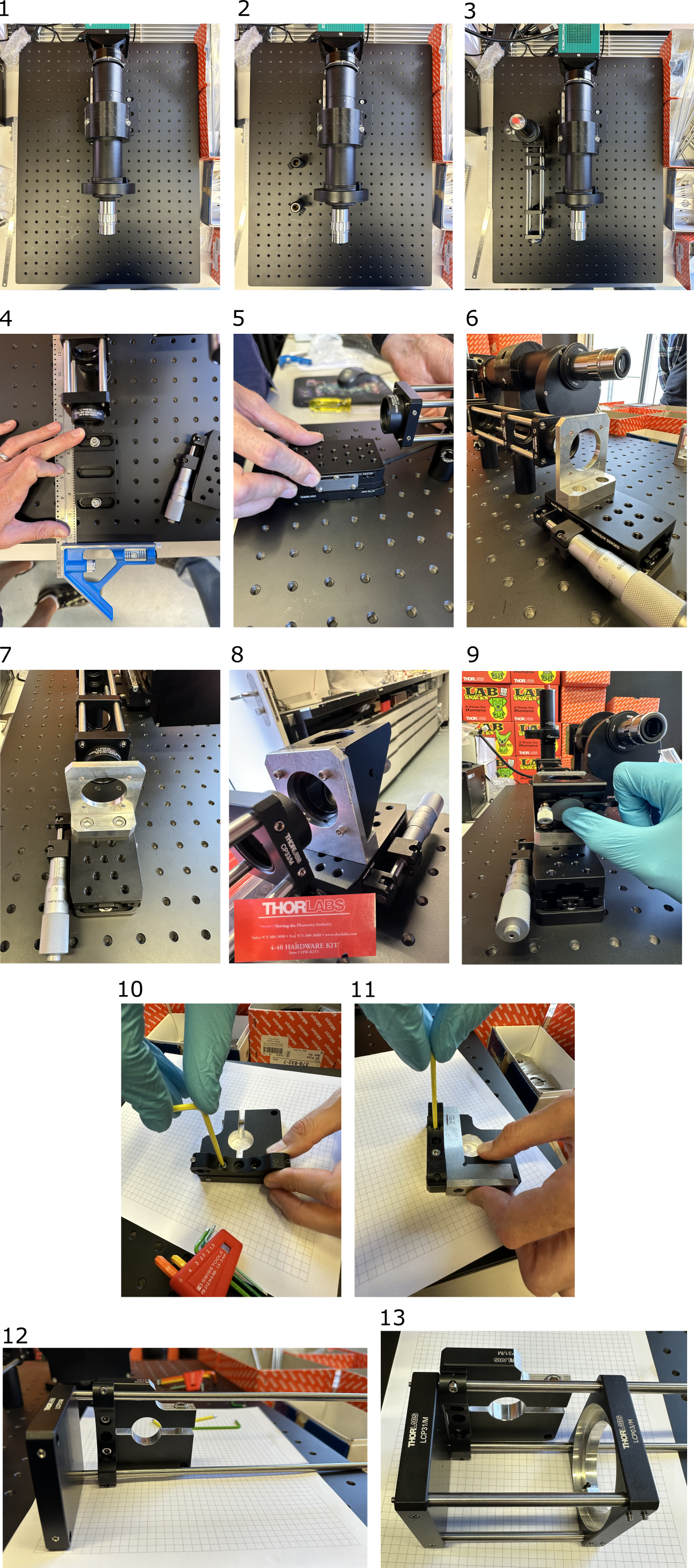
- Attach 40-mm optical posts to the empty cage plates.


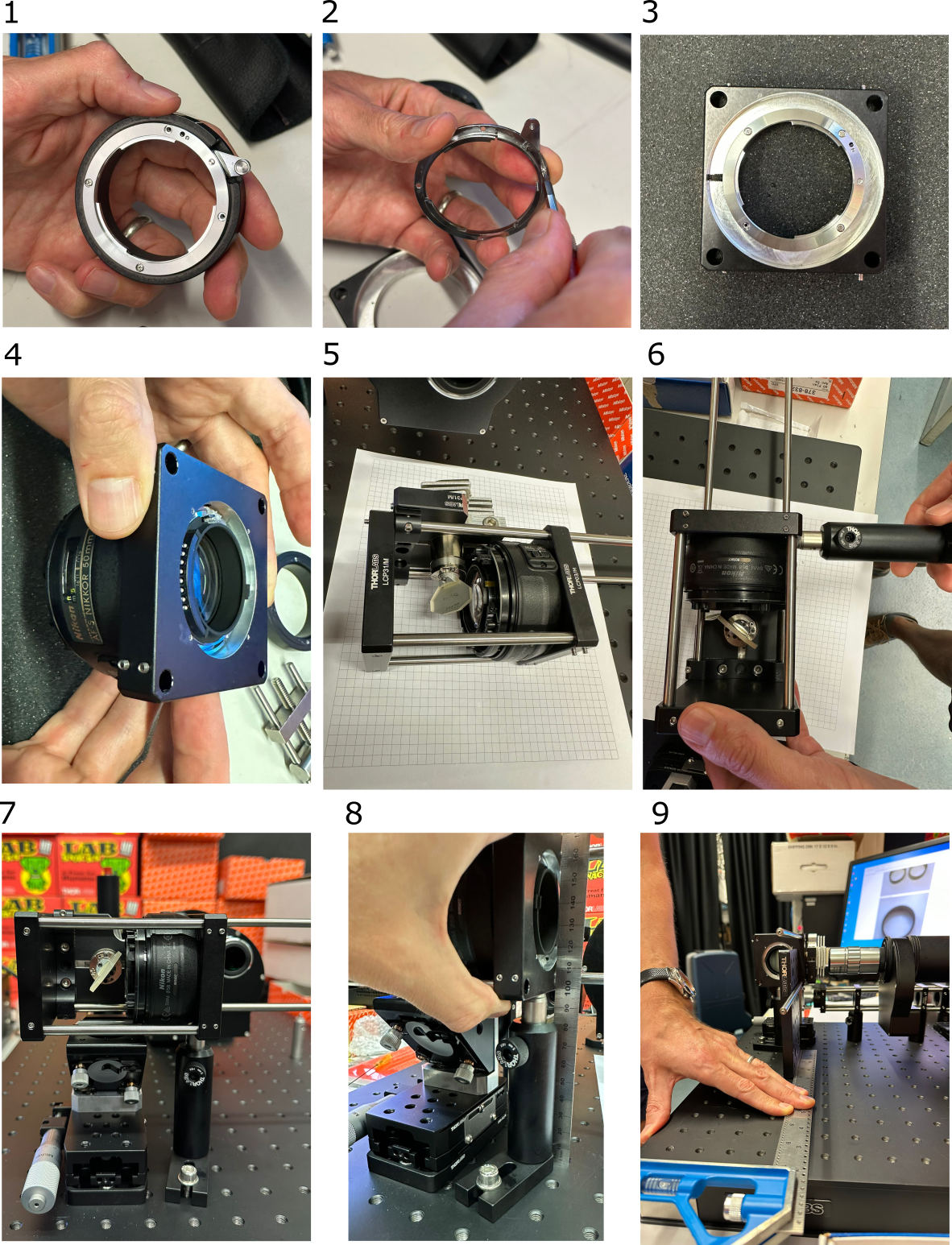
Refer to the mesoSPIM V5 wiki about 2x Nikon 50 mm f/1.4 G DLSR lenses modification
- Remove the small screws from the Thorlabs SM2NFM F-mount female adapter, and keep the ring and the screws.
- Remove the small lever from the F-mount ring.
- Mount the F-mount ring into the machined cage plate adapter. Use the screws you removed earlier.
- Insert and fix the modified Nikon objective into the F-mount.
- Mount the Nikon objective, the galvo assembly and the back LCP31/M plate on the cage rods.
- Attach the optical post.
- Place the assembly on the breadboard, with the galvo shifted about 5 mm to the left, compared to the center of the folding mirror.
- The height of the 60 mm cage plate must be 99-100 mm from the breadboard.
- The cage rods can be aligned to the breadboard using a smaller breadboard (or another rectangular machined piece of metal) and a try square.

The linear stage XRN25C/M for the right arm must be "converted", so the micrometer with the locking plate sides are swapped (micrometer moves to the right side of the stage). Back out the micrometer to the 25 mm reading before removing all three button head screws from the locking plate. Failure to do this will cause the stage to quickly retract to its minimum position when the micrometer is removed, potentially damaging the mechanism.

- Overview
- Room requirements
- Safety
- Parts list
-
Assembly
- Overview
- Detection arm
- Excitation arms
- Sample stages
- Electronics
- Lasers
- Immersion chambers (TODO)
- Front cover (with webcam)
- Enclosure (TODO)
- Usage
- Troubleshooting and typical errors (TODO)
- Maintenance(TODO)
- Technical notes