-
Notifications
You must be signed in to change notification settings - Fork 5
Excitation_laser_alignment
Nikita Vladimirov edited this page Nov 6, 2024
·
9 revisions
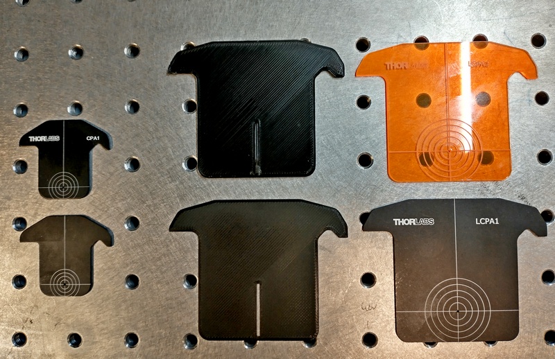
- 2x Thorlabs t-shirt alignment targets CPA1
- 2x custom 3D-printed 60-mm cage slit alignment targets LCPA1-slit, based on Thorlabs LCPA1 design.
- 1x Thorlabs LCPA1 60-mm cage alignment plate.
- 1x Thorlabs LCPA2 60 mm cage fluorescent alignment plate.

- Start the
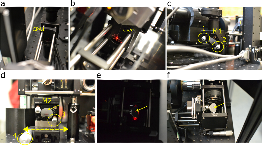
mesoSPIM_controlsoftware, switch excitation to left arm, and choose red, yellow or green laser at low intensity. Press Live button to trigger laser signal. Alternatively, use the laser combiner software to turn the laser on. - place the two CPA1 targets at the ends of the 30-mm cage, next to M1 and M2 folding mirrors (Fig. a, b).
- adjust the knobs of M1 (Fig. c) to align the laser beam to the second (more distant) target (Fig. b, correct alignment). Now the beam is co-axial to the 30-mm cage.
- observe the laser beam bleed-through at the back of mirror M2 (Fig. d, small arrow). Move the mirror M2 left/right (Fig. d, large arrow) on its carriage until the beam is centered and hits the upper quarter of the mirror back side. This corresponds to the mirror's optical center. Fix the carriage locking screw.
⚠️ Turn off the laser! After making sure the laser is off, look down at the galvo. Mirror M2 must be directly under the galvo (not shown). Move linear stage 4 for M2 position adjustment.⚠️ This is the most dangerous step, where laser can directly hit your eye. Make sure to turn the laser off before this step.- Turn the laser back on, and room lights off. The laser beam must be located at the center of the galvo, seen as a weak bleed-through at the galvo's back side (Fig. e, arrow). Adjust the beam position (actually angle) using knob 3.
From this point, knob 3 and linear stage 4 of folding mirror M2 will be the main alignment mechanisms.

These steps guide you through horizontal alignment of the light-sheet in the sample space, between the two excitation objectives.
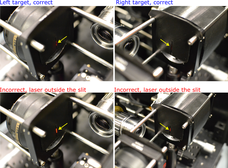
- Place the two custom 3D-printed 60-mm cage slit alignment targets LCPA1-slit into 60 mm cage, as close to excitation objectives as possible.
- start the
mesoSPIM_softwarein Live mode to generate a light-sheet in the left arm. - using knob 3 and linear stage 4 described above, adjust the light-sheet horizontal angle and position until it clearly goes through both slits. There should be no laser visible outside of the slits (this indicates misalignment). See figure below.

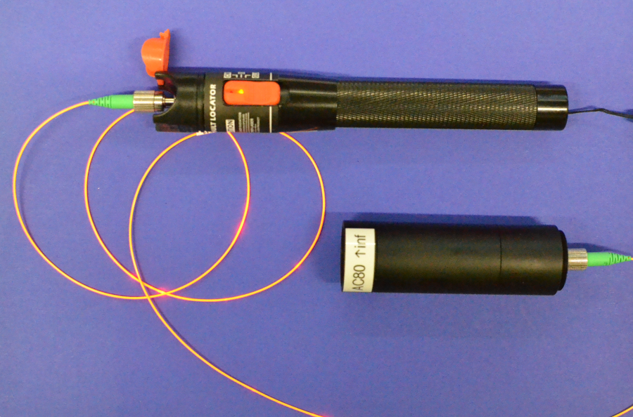
Sometimes your main laser combiner is not available, but you need a collimated laser beam. You can build a low-cost laser collimator from the following parts:
- Thorlabs achromat 80 mm AC254-080-A-ML, or 100 mm AC254-100-A-ML. The 80 mm gives more compact device, while the 100 mm gives better beam quality with less spherical aberration.
- lens tubes: SM1L20 + SM1L10 for 80 mm achromat, or SM1L40 for 100-mm achromat
- P3-460Y-FC-1 SM Patch Cable, 488 - 633 nm, FC/APC, Ø900 µm Jacket, 1 m
- SM1FCA FC/APC Fiber Adapter Plate with External SM1 (1.035"-40) Threads, Wide Key (2.2 mm)
- laser fault detector (power 10 or 20 mW), e.g. from AliExpress for about 10$.

- Overview
- Room requirements
- Safety
- Parts list
-
Assembly
- Overview
- Detection arm
- Excitation arms
- Sample stages
- Electronics
- Lasers
- Immersion chambers (TODO)
- Front cover (with webcam)
- Enclosure (TODO)
- Usage
- Troubleshooting and typical errors (TODO)
- Maintenance(TODO)
- Technical notes